Micron Technical Reference V9 Volume 1.pdf - 第275页
PROFLOW MODULE OVERVIEW Chapter Issue 2, Aug 14 Technical Reference Manual 11.1 CHAPTER 1 1 PROFLOW MODULE OVER VIEW Item Description Item Description 1 ProFlow Printhead Me chanism 3 ProFl ow T ransfer Head 2 ProFlow Pr…
PROACTIV
REPLACEMENT PROCEDURES
10.24 Technical Reference Manual Chapter Issue 5, Jan 15
the unit away safely and securely.
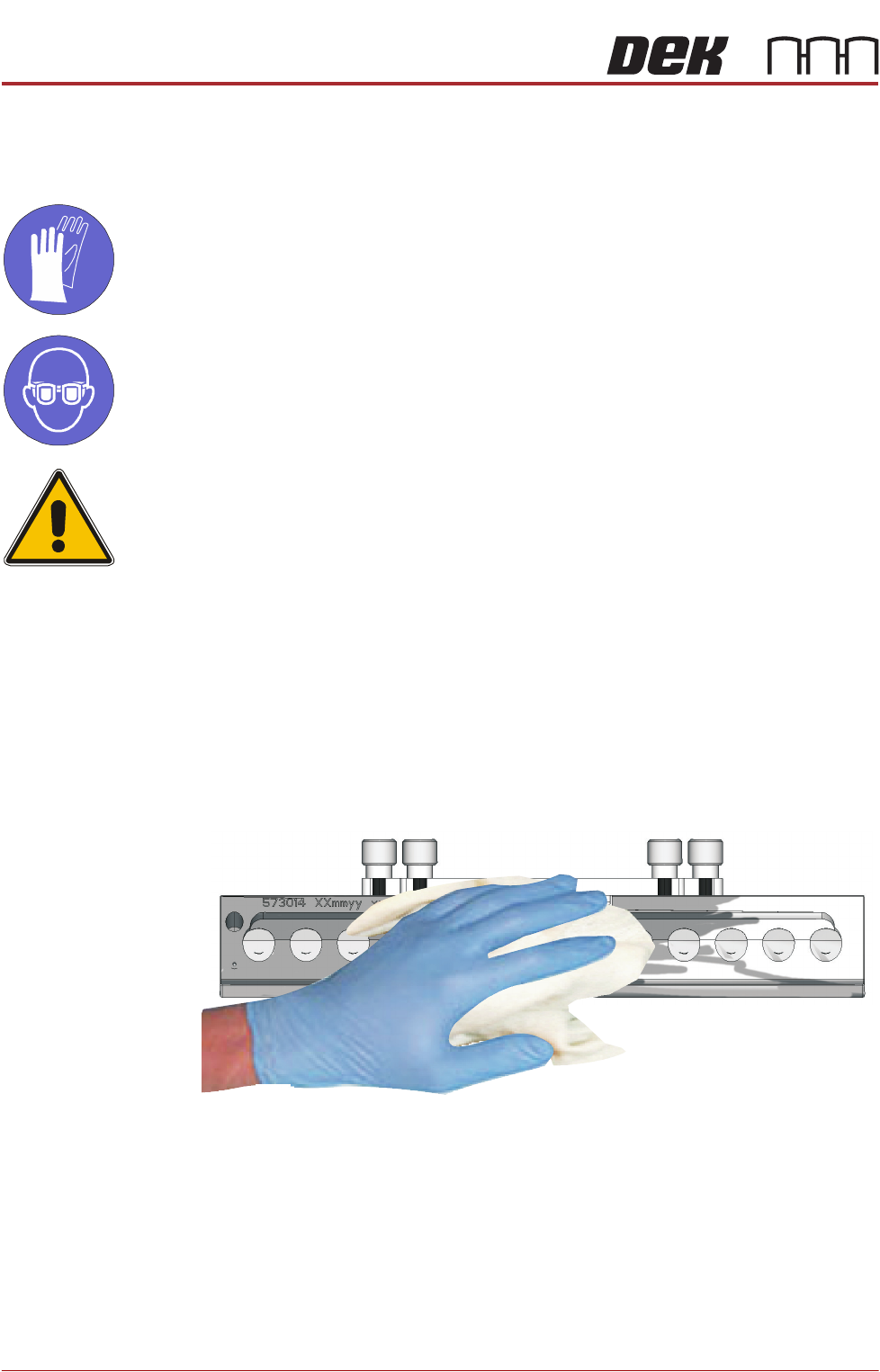
Cleaning Guidance
MANDATORY
TOXIC CHEMICALS MAY BE PRESENT. SAFETY GLOVES MUST BE WORN.
MANDATORY
TOXIC CHEMICALS MAY BE PRESENT. EYE PROTECTION MUST BE WORN.
CAUTION
RECOMMENDED SOLVENTS. ANY SOLVENTS USED MUST COMPLY WITH
LOCAL ENVIRONMENTAL GUIDELINES. ASM RECOMMEND USING SOLVENTS
THAT ARE ENVIRONMENTALLY FRIENDLY, IE CFC FREE AND WATER BASED.
SOLVENTS USED MUST HAVE FAST EVAPORATION RATES AND FLASHPOINT
SPECIFICATIONS GREATER THAN 39ºC.
NOTE
Immersion of any part of the ProActiv unit in liquids causes irreparable damage
to the unit. It may also cause permanent damage when fitted to the printer.
1. Remove the ProActive squeegee units using the Removal procedure (pre-
vious section).
2. Using an IPA impregnated wipe (Part No: 11508), thoroughly clean all
exterior surfaces of each squeegee.
NOTE
Do not subject the unit, or its cable, to any undue stress or strain whilst
cleaning.
3. Stow the units away carefully and safely.
PROFLOW MODULE
OVERVIEW
Chapter Issue 2, Aug 14 Technical Reference Manual 11.1
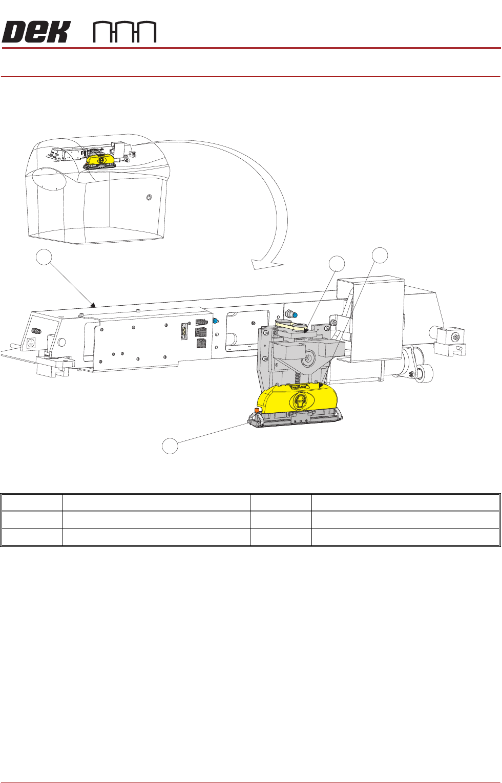
CHAPTER 11 PROFLOW MODULE
OVERVIEW
Item Description Item Description
1 ProFlow Printhead Mechanism 3 ProFlow Transfer Head
2 ProFlow Pressure Mechanism 4 Print Carriage
1
2
3
4
PROFLOW MODULE
OVERVIEW
11.2 Technical Reference Manual Chapter Issue 2, Aug 14
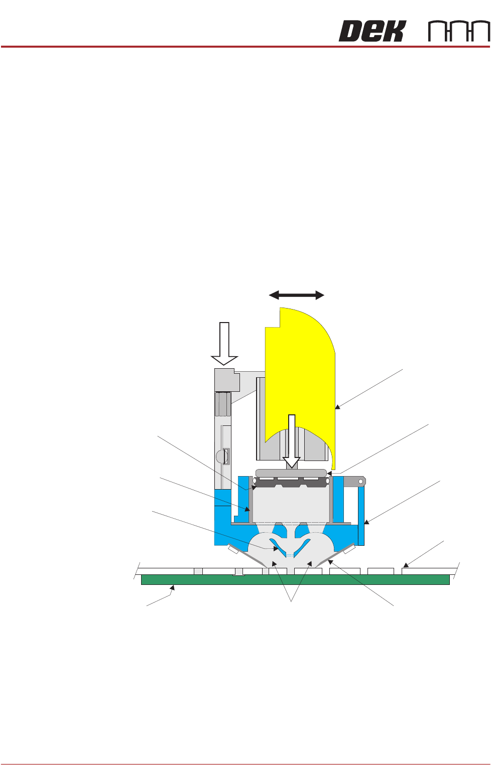
The ProFlow mechanism is driven backwards and forwards across the stencil
by the print carriage applying printable material directly onto the stencil. This
alleviates the need for squeegees and a paste dispenser.
The ProFlow mechanism is raised and lowered, to the stencil by means of a
stepper motor, applying a downward force directly onto the stencil providing a
positive seal between the transfer head and stencil. This eliminates leakage of
print material above the stencil.
Paste pressure (pneumatic), is applied to the piston crosshead exerting a force
onto the print material which, in turn, forces print material into the ProFlow
conditioning chamber and into the stencil apertures.
As the unit moves across the stencil the trailing wiper, within the transfer head,
lifts the print material from the stencil surface, clearing the stencil of print
material and creating a rolling movement of material within the conditioning
chamber.
Figure 11-1 ProFlow Cross Section (with cassette option)
ProFlow Pressure
Mechanism
Transfer
Head
Stencil
Board
ProFlow Movement (Y Axis)
Wiper
Piston
Crosshead
Pneumatic
Pressure
System Pressure
Print Material
Side Chambers
Cassette
Nozzle
Cassette
Plunger