Micron Technical Reference V9 Volume 1.pdf - 第277页
PROFLOW MODULE OVERVIEW Chapter Issue 2, Aug 14 Technical Reference Manual 11.3 The sensor used to detect paste is: • ProFlow Paste Level Sensor - Giant Magneto resistive (displays to the operator a percentage of paste r…
PROFLOW MODULE
OVERVIEW
11.2 Technical Reference Manual Chapter Issue 2, Aug 14
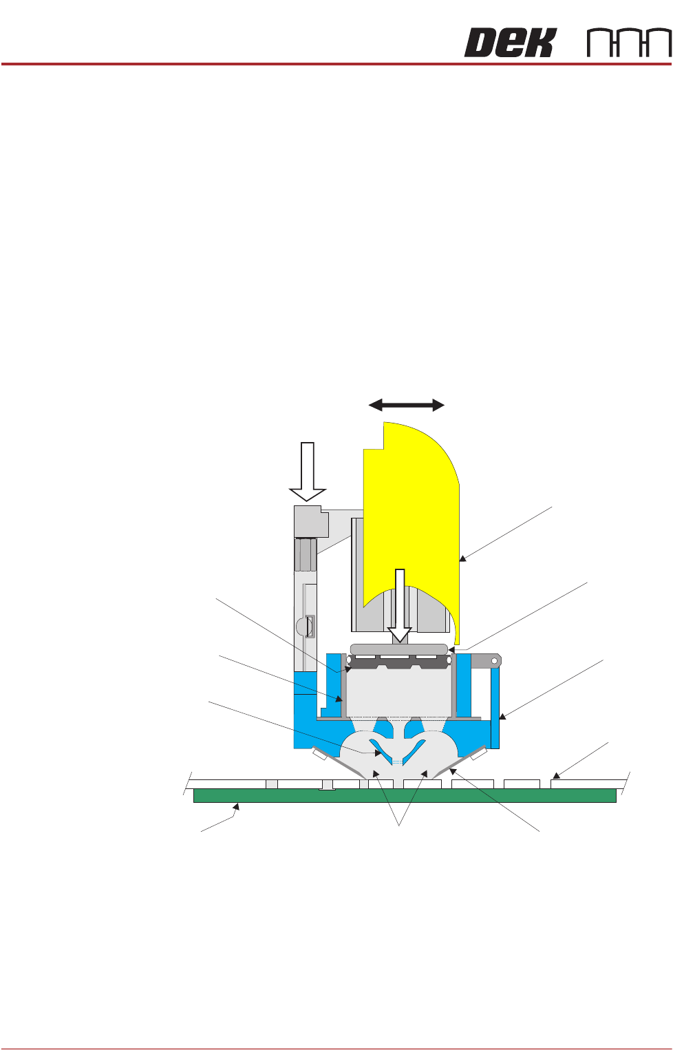
The ProFlow mechanism is driven backwards and forwards across the stencil
by the print carriage applying printable material directly onto the stencil. This
alleviates the need for squeegees and a paste dispenser.
The ProFlow mechanism is raised and lowered, to the stencil by means of a
stepper motor, applying a downward force directly onto the stencil providing a
positive seal between the transfer head and stencil. This eliminates leakage of
print material above the stencil.
Paste pressure (pneumatic), is applied to the piston crosshead exerting a force
onto the print material which, in turn, forces print material into the ProFlow
conditioning chamber and into the stencil apertures.
As the unit moves across the stencil the trailing wiper, within the transfer head,
lifts the print material from the stencil surface, clearing the stencil of print
material and creating a rolling movement of material within the conditioning
chamber.
Figure 11-1 ProFlow Cross Section (with cassette option)
ProFlow Pressure
Mechanism
Transfer
Head
Stencil
Board
ProFlow Movement (Y Axis)
Wiper
Piston
Crosshead
Pneumatic
Pressure
System Pressure
Print Material
Side Chambers
Cassette
Nozzle
Cassette
Plunger
PROFLOW MODULE
OVERVIEW
Chapter Issue 2, Aug 14 Technical Reference Manual 11.3
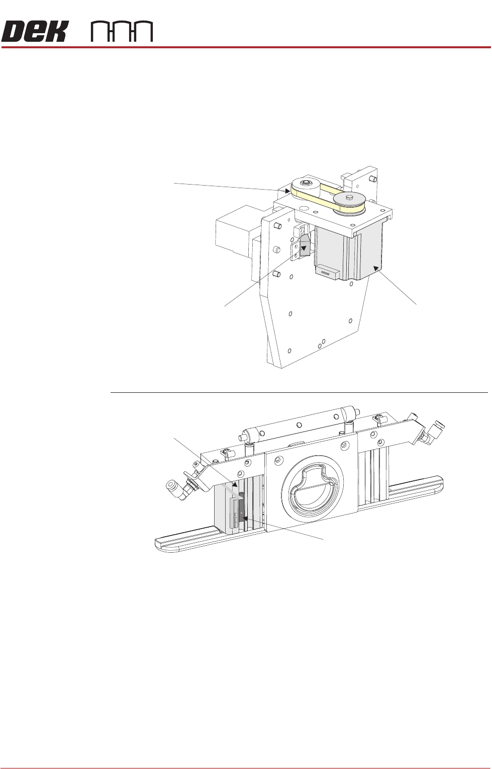
The sensor used to detect paste is:
• ProFlow Paste Level Sensor - Giant Magneto resistive (displays to the
operator a percentage of paste remaining (time-to-go))
The sensor is fitted to the left hand side pressure mechanism pneumatic
actuator, as shown in the figure below.
Figure 11-2 ProFlow Sensor and Stepper Motor Locations
View on Rear of ProFlow Printhead Mechanism
ProFlow Home Sensor
Drive Belt
Stepper Motor
View on Front of ProFlow Pressure Mechanism (cover removed)
Pneumatic Actuator
15
0
30
Paste Level Sensor
PROFLOW MODULE
OVERVIEW
11.4 Technical Reference Manual Chapter Issue 2, Aug 14
The following configurations of ProFlow are available for use on the machine:
Cassette The ProFlow cassette is available in 300mm size only (capacity approximately
800g - 850g solder paste).
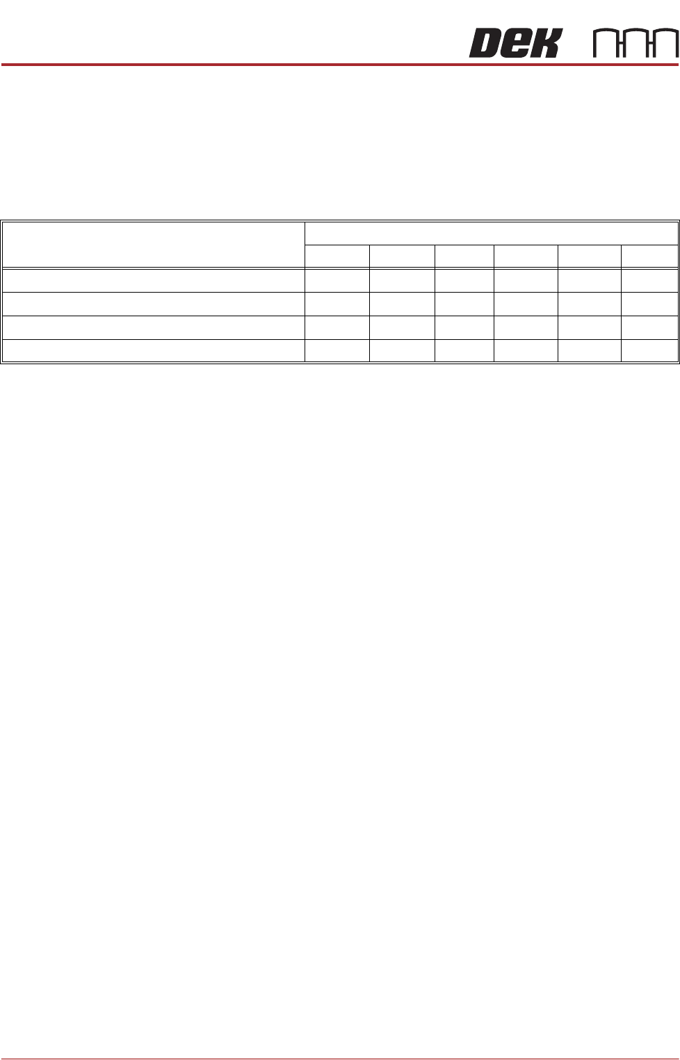
Transfer Head The table below lists the types of optional transfer head units and sizes
available, for use with ProFlow:
NOTE
All of the above cassette transfer heads are fitted with the standard 300mm
cassette and 300mm piston crosshead. A dedicated piston crosshead is
required for each rechargeable transfer head size.
Transfer Head Type
Transfer Head Sizes (mm)
150 300 350 400 450 500
Cassette Type (single conditioning chamber) Yes Yes Yes
Cassette Type (dual conditioning chamber) Yes Yes Yes
Rechargeable Type (single conditioning chamber) Yes Yes Yes Yes Yes
Rechargeable Type (dual conditioning chamber) Yes Yes Yes Yes Yes Yes