Micron Technical Reference V9 Volume 1.pdf - 第283页
PROFLOW MODULE REPLACEMENT PROCEDURES Chapter Issue 2, Aug 14 Technical Reference Manual 11.9 mechanism from the print carriage. Removing Drip T ray If a stencil cha nge mechanism is fitted, carry out the following: 1. C…
PROFLOW MODULE
REPLACEMENT PROCEDURES
11.8 Technical Reference Manual Chapter Issue 2, Aug 14
REPLACEMENT PROCEDURES
Squeegees to
ProFlow
Instances may occur when the machine is required to print using the ProFlow
module configuration. The following procedure details how to revert the
machine from squeegee use to the ProFlow configuration:
Removing
Squeegee
Mechanism
1. Select Open Cover Commands.
2. Select Carriage To Front.
3. Select Back.
4. Select Shut Down.
5. Select Continue.
6. Switch the mains isolator to OFF.
7. Remove the squeegees, if fitted.
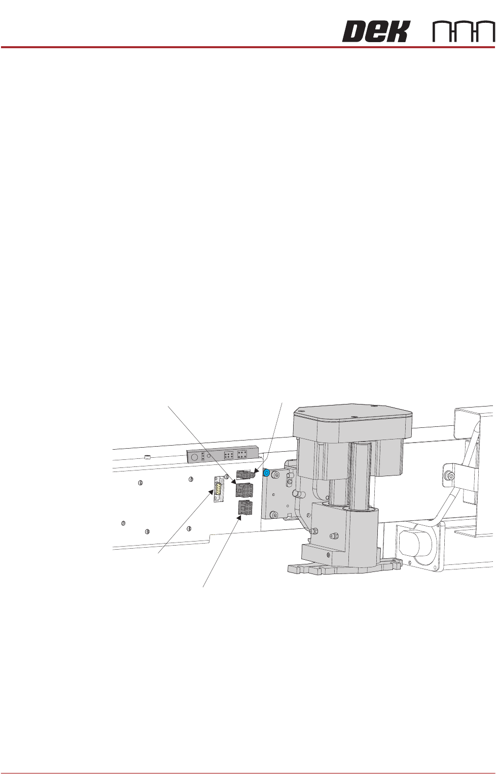
8. Disconnect the four squeegee mechanism connectors from the print car-
riage, left hand side:
• Rear Squeegee Motor
• Front Squeegee Motor
• Home Sensors
• Squeegee Pressure Amplifier
9. Loosen the four captive screws securing the squeegee printhead mecha-
nism to the print carriage using a 4mm Allen key. Carefully remove the
Rear Squeegee
Motor (9SK17)
Front Squeegee
Motor (9SK16)
Home Sensors
(9SK08)
Squeegee Pressure
Amplifier (N3SK16)
PROFLOW MODULE
REPLACEMENT PROCEDURES
Chapter Issue 2, Aug 14 Technical Reference Manual 11.9
mechanism from the print carriage.
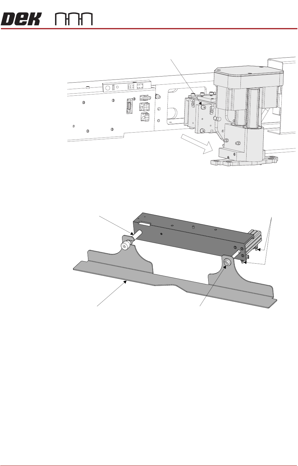
Removing Drip Tray If a stencil change mechanism is fitted, carry out the following:
1. Close the speed control valves on the drip tray actuator.
2. Remove the securing screw attaching the drip tray to the actuator piston.
3. Slide the drip tray off the bearing on the drip tray guide shaft.
Captive Screw (in 4 positions)
Drip Tray
Drip Tray Guide Shaft
Securing Screw
Speed Control Valves
PROFLOW MODULE
REPLACEMENT PROCEDURES
11.10 Technical Reference Manual Chapter Issue 2, Aug 14
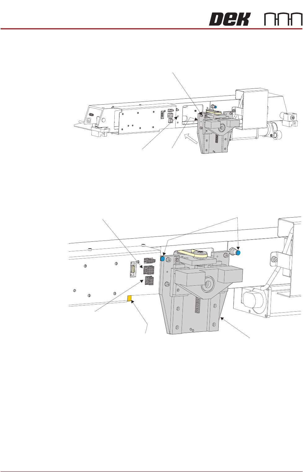
Fitting ProFlow 1. Carefully position the ProFlow printhead mechanism so that both locating
dowels locate into the print carriage locating holes. Secure the unit to the
print carriage by means of the four captive screws.
2. Connect the following connectors to the print carriage, left hand side:
• ProFlow Motor
• Home Sensor
3. Fit the pressure mechanism part of the ProFlow unit to the ProFlow print-
head mechanism bearing block by means of the two securing bolts. Tighten
Captive Screw (in 4 positions)
Locating Dowel
(in 2 positions)
Print Carriage Locating
Hole (in 2 positions)
Pneumatic Connectors
ProFlow Motor
(9SK17)
Home Sensor
(9SK08)
ProFlow Paste Level
Sensor (9PL61)
ProFlow Printhead
Mechanism