Micron Technical Reference V9 Volume 1.pdf - 第45页
COVERS PRINTER COVERS Chapter Issue 11, Jan 17 Technical Reference Manual 3.3 NOTE Some of the covers can on ly be removed in a specific order due to the covers interlocking with each other . Cover Removal Before removin…
COVERS
PRINTER COVERS
3.2 Technical Reference Manual Chapter Issue 11, Jan 17
Earth Bonding Apart from the Type 3, 4 and 5 covers printers, which use metal covers to make
the bond, all external metal surfaces are mechanically and electrically bonded
to the printer earth point. The bonding wire used is identified by its green and
yellow insulation and is commonly used to earth bond throughout. Care should
be taken when removing these links that they are secured tightly and cleanly,
when replaced.
NOTE
The EPA cover package option is available for the Type 2 Cover printer only. Its
covers are bonded through a series clips and sprung contact studs. The covers
themselves have an electrically conductive conformal coating to dissipate static
electricity. For the Electrostatic Protected Area to work effectively, all fixings are
to be kept clean, all panels must be fitted correctly, and the printhead cover
closed.
Safety Interlocks The safety features designed into the printer are for the protection of all
operators and maintenance personnel. ASM strongly recommend safety
devices are never overridden.
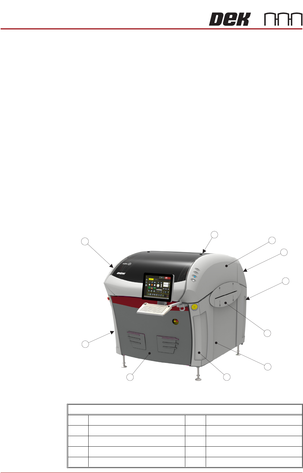
Type 1 Covers In order to protect personnel and prevent damage, eight covers are fitted to the
printer. The upper part of the printer is protected by the sliding printhead cover,
one rear lifting printhead cover and two upper side panels which house the
control switches.
Front Left Quarter View
1 Printhead Cover 6 Side Panel (in 2 positions)
2 Right Hand Upper Side Panel 7 Left Hand Front Corner Panel
3 Rear Cover 8 Front Panel
4 Right Hand Lower Side Panel 9 Left Hand Lower Corner Panel
5 Safety Cover (in 2 positions) 10 Left Hand Upper Side Panel
1
2
3
4
5
6
7
8
9
10
COVERS
PRINTER COVERS
Chapter Issue 11, Jan 17 Technical Reference Manual 3.3
NOTE
Some of the covers can only be removed in a specific order due to the covers
interlocking with each other.
Cover Removal Before removing covers ensure that the supplies (air and electrical) have been
isolated from the printer.
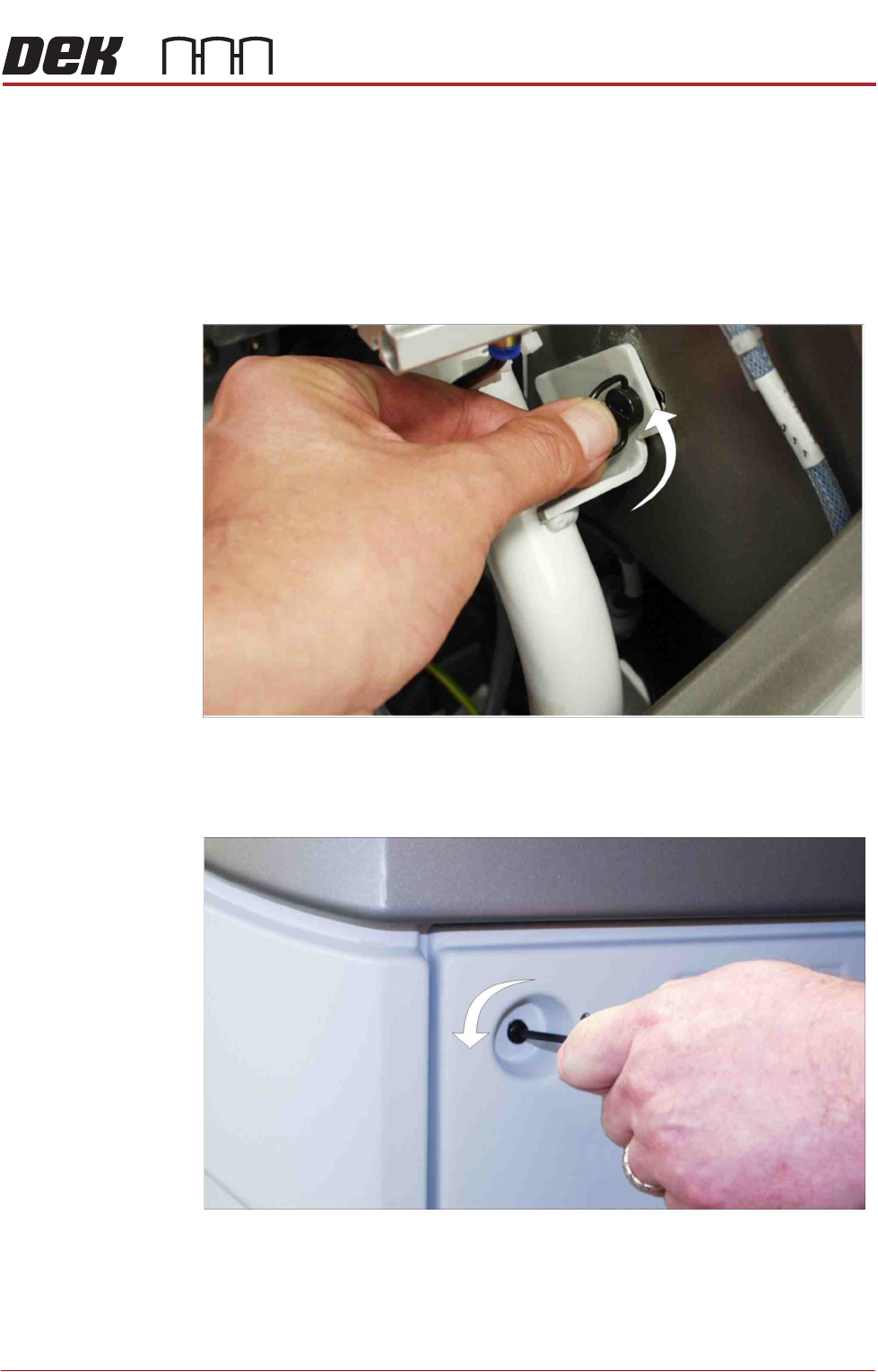
Ring Head Quarter-
Turn Fasteners
To remove a panel secured with ring head quarter-turn fasteners, turn the
fastener anti-clockwise by a quarter-turn and pull out.
Figure 3-1 Ring Head Quarter-Turn Fastener
Button Head
Quarter-Turn
Fasteners
To remove a panel secured with button head quarter-turn fasteners, using a
4mm Allen key, turn the fastener anti-clockwise by a quarter-turn and pull out.
Figure 3-2 Button Head Quarter-Turn Fastener
COVERS
PRINTER COVERS
3.4 Technical Reference Manual Chapter Issue 11, Jan 17
Front Panel The front panel is secured by a ring head quarter-turn fastener and a button
head quarter-turn fastener.
1. To remove the front panel of the printer, open the front printhead cover and
locate the two quarter-turn fasteners on the inside of the panel.
2. After releasing the fasteners, tilt the top of the panel away from the printer
and lift clear of the guide pins that locate the panel to the printer frame.
Rear Panel Removal of the rear panel requires a 4mm Allen key to release the two button
head quarter-turn fasteners located externally at the top corners of the panel.
After releasing the fasteners, push downwards on the panel to clear the rear
printhead cover, tilt the top of the panel away from the printer and lift clear of the
guide pins that locate the panel to the printer frame.
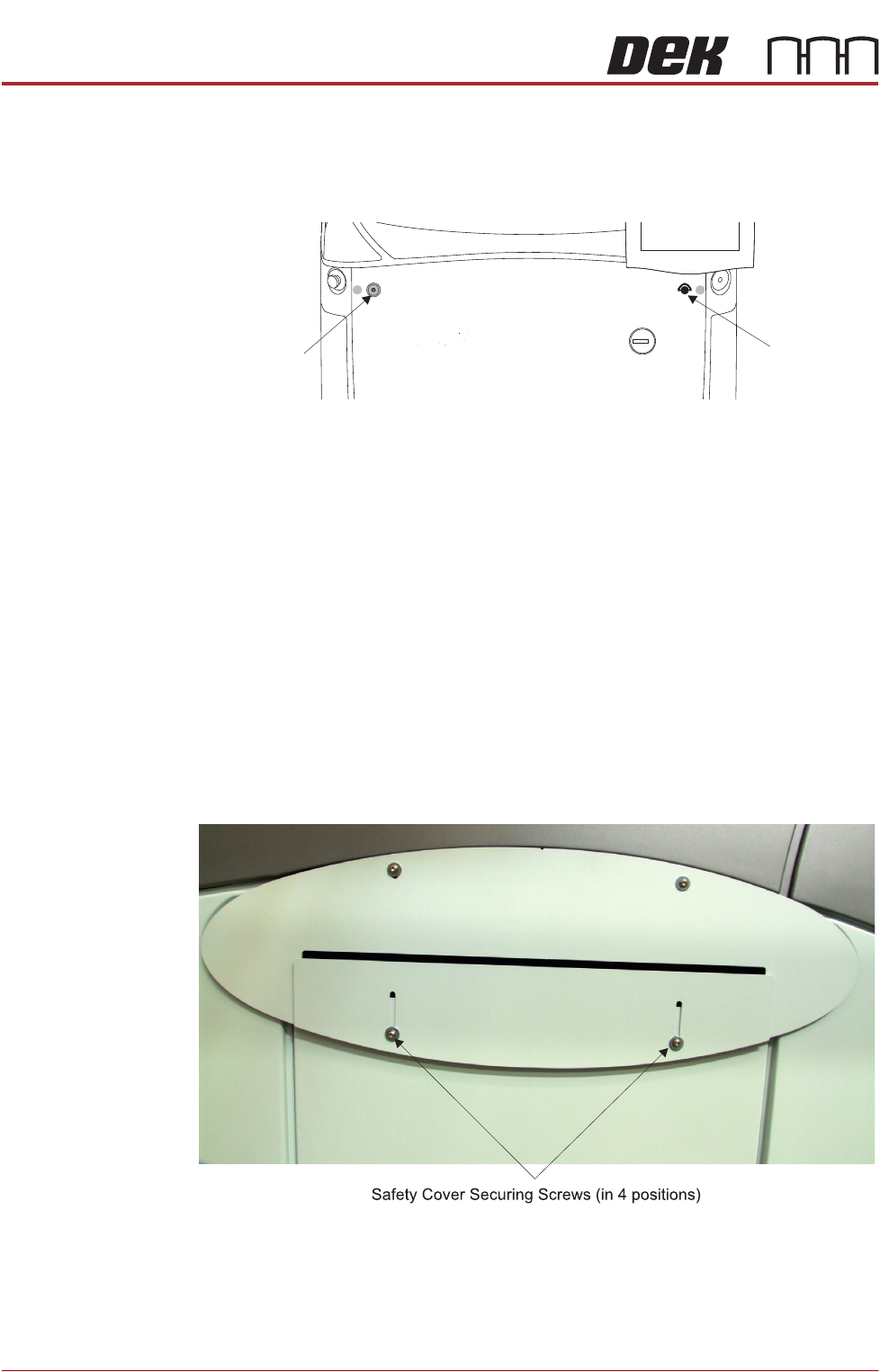
Safety Covers Safety covers are fitted to the side panels to protect personnel from inadvertent
access to the board entry/exit ports.
NOTE
The lower section of the safety panel can be adjusted to accommodate the
thickness of the product.
To remove the safety cover, remove the four securing screws.
Front Panel
Button Head
Quarter-Turn
Fastener
Front Panel
Ring Head
Quarter-Turn
Fastener