Micron Technical Reference V9 Volume 1.pdf - 第65页
COVERS PRINTER COVERS Chapter Issue 11, Jan 17 Technical Reference Manual 3.23 Cover Removal Before removing covers ensure that the supplie s (air and electrical) have been isolated from the printer . Front Panel T o rem…
COVERS
PRINTER COVERS
3.22 Technical Reference Manual Chapter Issue 11, Jan 17
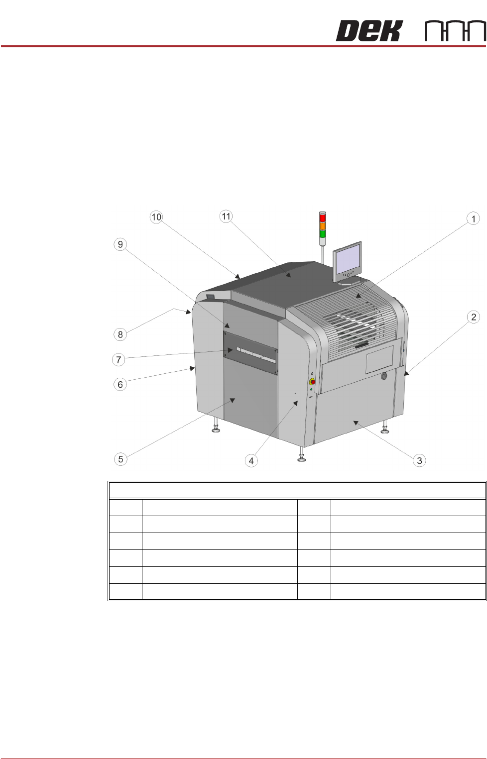
Type 3 Covers In order to protect personnel and prevent damage to the printer, eight panels
are fitted around the base of the printer.
• Front Panel
• Rear Panel
• Corner Panels (4 positions)
• Lower Side Panels (2 positions)
The upper part of the printer is protected by the front printhead cover, the rear
fixed printhead cover, the top panel and two upper side panels.
NOTE
Some of the covers can only be removed in a specific order due to the covers
interlocking with each other.
Front Left Quarter View
1 Front Printhead Cover 7 Safety Cover (2 positions)
2 Front Right Hand Corner Panel 8 Rear Panel
3 Front Panel 9 Upper Side Panel (2 positions)
4 Front Left Hand Corner Panel 10 Rear Fixed Printhead Cover
5 Lower Side Panel (2 positions) 11 Top Panel
6 Rear Corner Panel (2 positions)
COVERS
PRINTER COVERS
Chapter Issue 11, Jan 17 Technical Reference Manual 3.23
Cover Removal Before removing covers ensure that the supplies (air and electrical) have been
isolated from the printer.
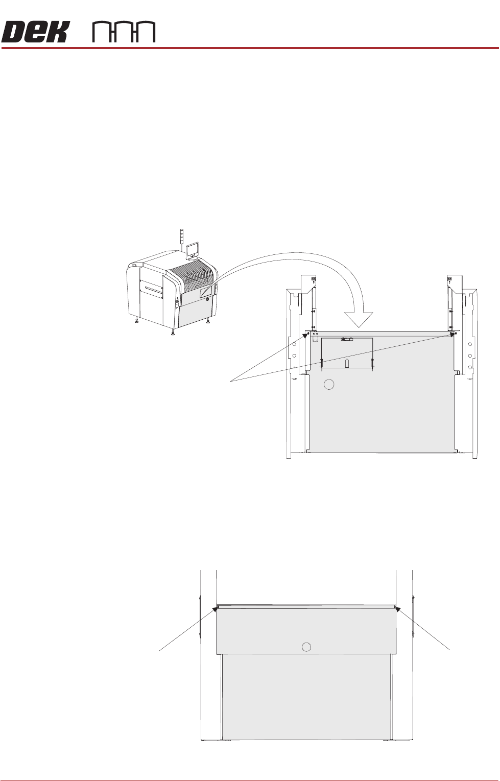
Front Panel To remove the front panel, carry out the following:
1. Open the front printhead cover.
2. Open the keyboard stowage door.
3. Disconnect the keyboard from the 4 port USB hub.
4. Remove the keyboard from its stowage.
5. Using a 4mm Allen key, undo the two captive screws on the rear side of the
panel.
6. Tilt the top of the panel away from the printer and lift the panel clear, taking
care not to damage the earth cable.
Rear Panel To remove the rear panel, carry out the following:
1. Using a 4mm Allen key, undo the two captive screws.
M5 Captive Screws
View on Rear of Front Panel
M5 Captive Screw
M5 Captive Screw
View on Rear of Machine
COVERS
PRINTER COVERS
3.24 Technical Reference Manual Chapter Issue 11, Jan 17
2. Tilt the top of the panel away from the printer and lift the panel clear, taking
care not to damage the earth cable.
Safety Covers To remove the rear fixed printhead cover, carry out the following:
1. Remove the rear panel (as detailed previously).
2. Using an 4mm Allen key, undo the two captive screws.
3. Remove the earth cable from the cover and lift the cover clear of the printer.
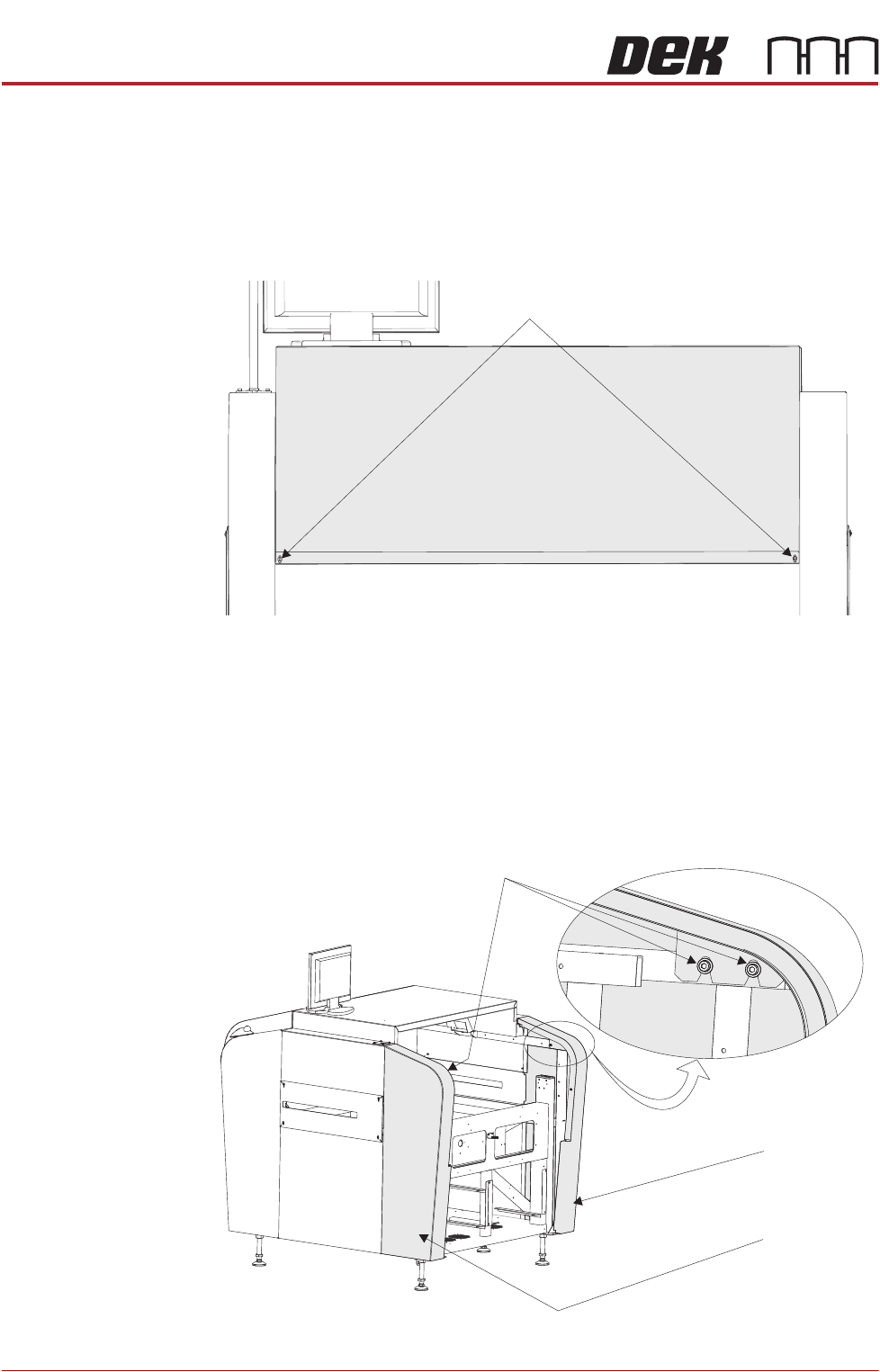
Rear Corner Panels To remove the rear corner panels, carry out the following:
1. Remove the rear panel (as detailed previously).
2. Remove the rear fixed printhead cover (as detailed previously).
3. Using an 4mm Allen key, undo the appropriate two captive screws.
4. Lift the panel clear of the printer, taking care not to damage the earth cable.
View on Rear of Machine
M5 Cap Screwstive
View on Rear - Right Quarter
M5 Cap Screwstive
Left Rear
Corner Panel
Right Rear
Corner Panel