Micron Technical Reference V9 Volume 1.pdf - 第88页
COVERS PRINTER COVERS 3.46 Technical Reference Manual Chapter Issue 11, Jan 17 clockwise and pull the contact assembly away from the E Stop body . 6. Repeat Steps 1, 3 and 4 for th e other lower side panel, if required. …
COVERS
PRINTER COVERS
Chapter Issue 11, Jan 17 Technical Reference Manual 3.45
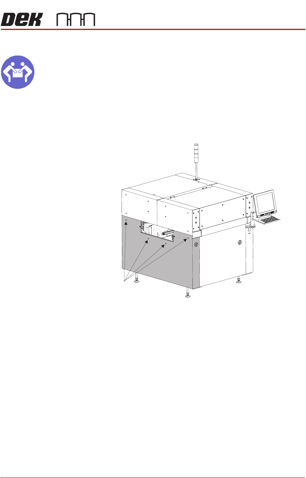
Lower Side Panels
MANDATORY
HEAVY OBJECT. LIFTING OR RESITING MUST BE UNDERTAKEN BY TWO
PEOPLE.
To remove the lower side panels, carry out the following:
1. Remove the corresponding safety cover (as detailed previously).
2. Open the front printhead cover.
3. Using an 4mm Allen key, undo the two captive screws.
4. Tilt the top of the panel away from the printer and lift the panel clear, taking
care not to damage the earth cable.
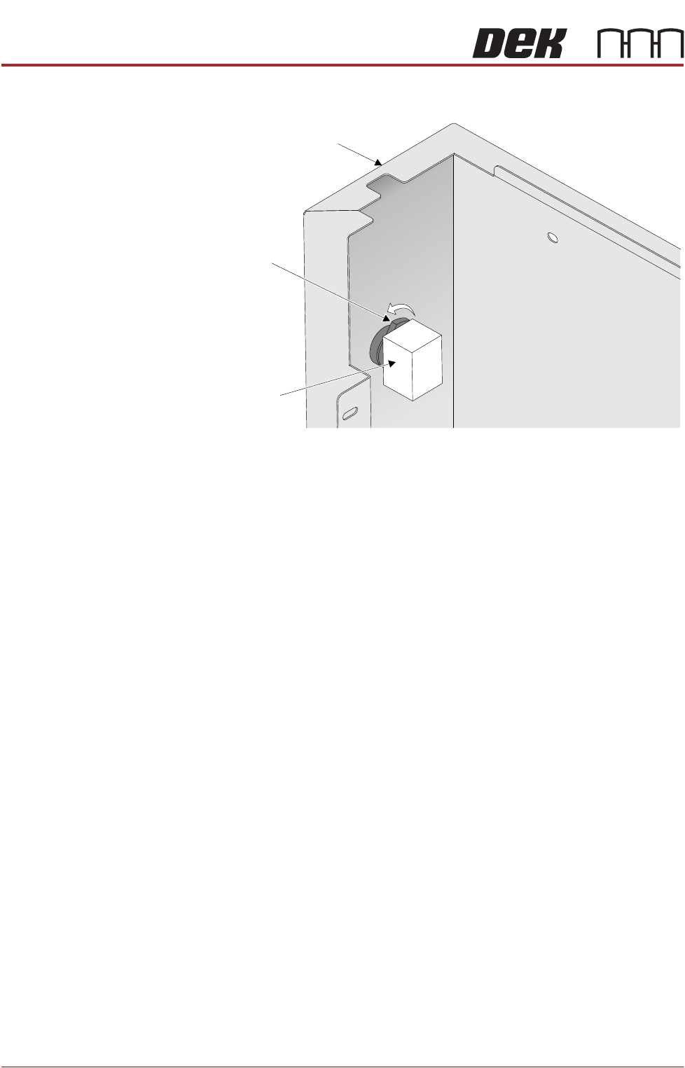
5. To disconnect the E Stop from the lower left side panel, turn the latch anti-
Front Left Quarter View
Captive Screws
COVERS
PRINTER COVERS
3.46 Technical Reference Manual Chapter Issue 11, Jan 17
clockwise and pull the contact assembly away from the E Stop body.
6. Repeat Steps 1, 3 and 4 for the other lower side panel, if required.
7. To disconnect the ESD bonding point locate the inline filter and remove the
spade connector.
Latch
Contact Assembly
Left Hand Lower Side Panel
View on Rear of E Stop
COVERS
PRINTER COVERS
Chapter Issue 11, Jan 17 Technical Reference Manual 3.47
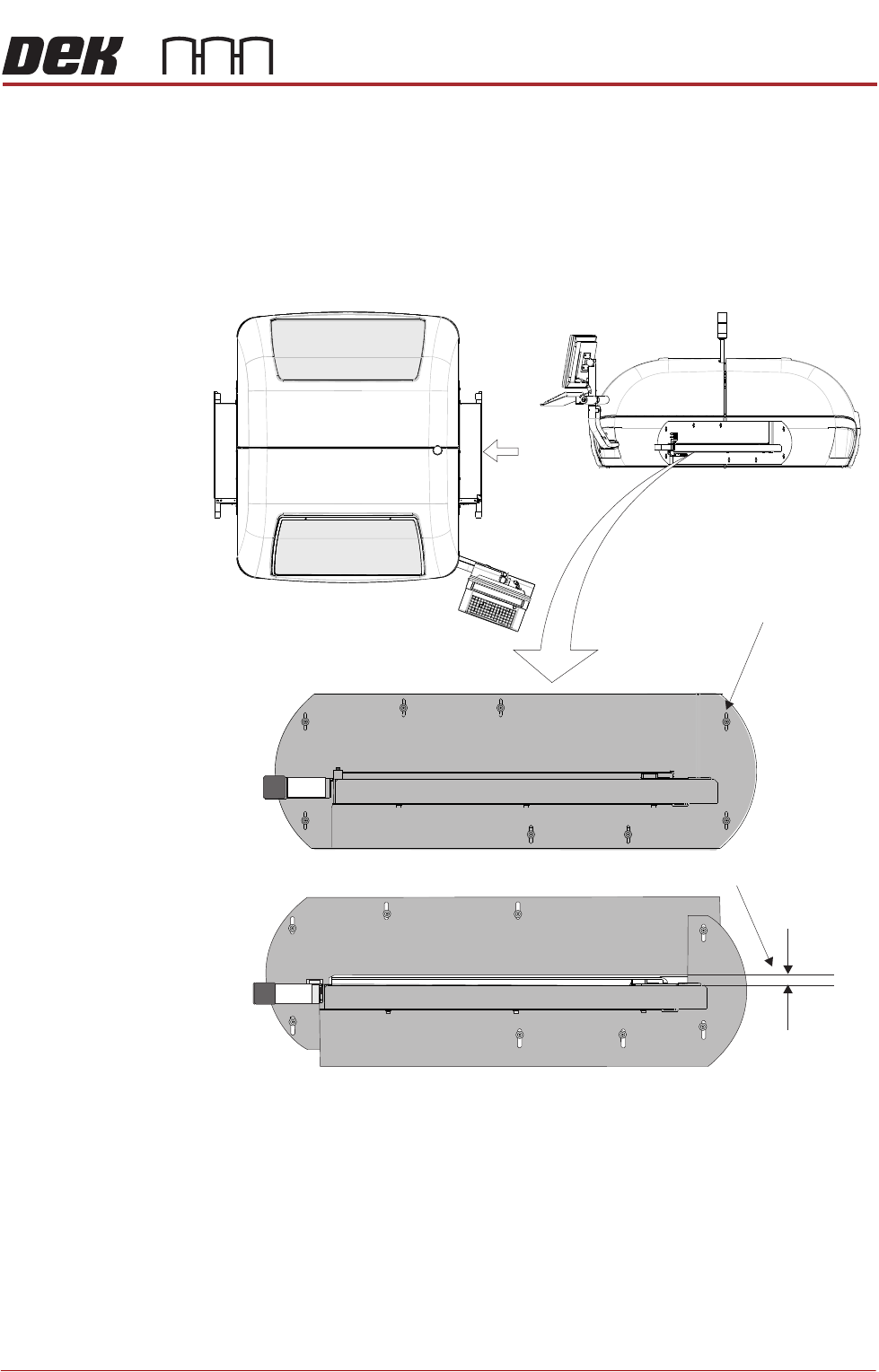
High Throughput Conveyor Option
Safety Covers Where the High Throughput Conveyor (HTC) option is used, the transport rails
extend out beyond the normal printer footprint. Special safety covers have been
provided in place of the standard safety covers (see also Type 2 Covers).
NOTE
The safety panel can be adjusted to accommodate the thickness of the product.
Figure 3-10 HTC Safety Covers
The covers are fitted to the side panels to protect personnel from inadvertent
access to the board entry/exit ports.
A pair of HTC safety covers are mounted on both the left and right hand sides
of the printer. The covers have slotted holes on the two cover halves allowing
the user to set sufficient gap for the product to be moved into and out of the
printer without restriction, while still protecting the operator from potential harm.
To remove the safety cover, remove the safety cover securing screws.
View on Arrow A
(top part of machine)
Gap Adjustment Slots
Set Gap > Product Thickness
HTC Safety Covers
(showing the two halves)
A