Micron Technical Reference V9 Volume 1.pdf - 第90页
COVERS PRINTER COVERS 3.48 Technical Reference Manual Chapter Issue 11, Jan 17 Electrostatic Protected Area (EP A ) The EP A cover package option is available for t he T ype 2 Cover printer only . Each panel on the prin …
COVERS
PRINTER COVERS
Chapter Issue 11, Jan 17 Technical Reference Manual 3.47
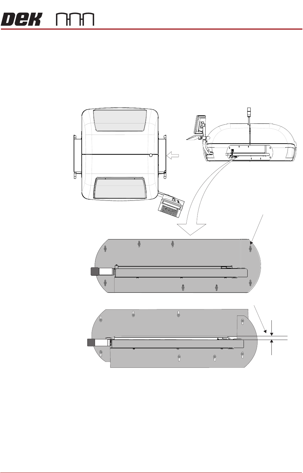
High Throughput Conveyor Option
Safety Covers Where the High Throughput Conveyor (HTC) option is used, the transport rails
extend out beyond the normal printer footprint. Special safety covers have been
provided in place of the standard safety covers (see also Type 2 Covers).
NOTE
The safety panel can be adjusted to accommodate the thickness of the product.
Figure 3-10 HTC Safety Covers
The covers are fitted to the side panels to protect personnel from inadvertent
access to the board entry/exit ports.
A pair of HTC safety covers are mounted on both the left and right hand sides
of the printer. The covers have slotted holes on the two cover halves allowing
the user to set sufficient gap for the product to be moved into and out of the
printer without restriction, while still protecting the operator from potential harm.
To remove the safety cover, remove the safety cover securing screws.
View on Arrow A
(top part of machine)
Gap Adjustment Slots
Set Gap > Product Thickness
HTC Safety Covers
(showing the two halves)
A
COVERS
PRINTER COVERS
3.48 Technical Reference Manual Chapter Issue 11, Jan 17
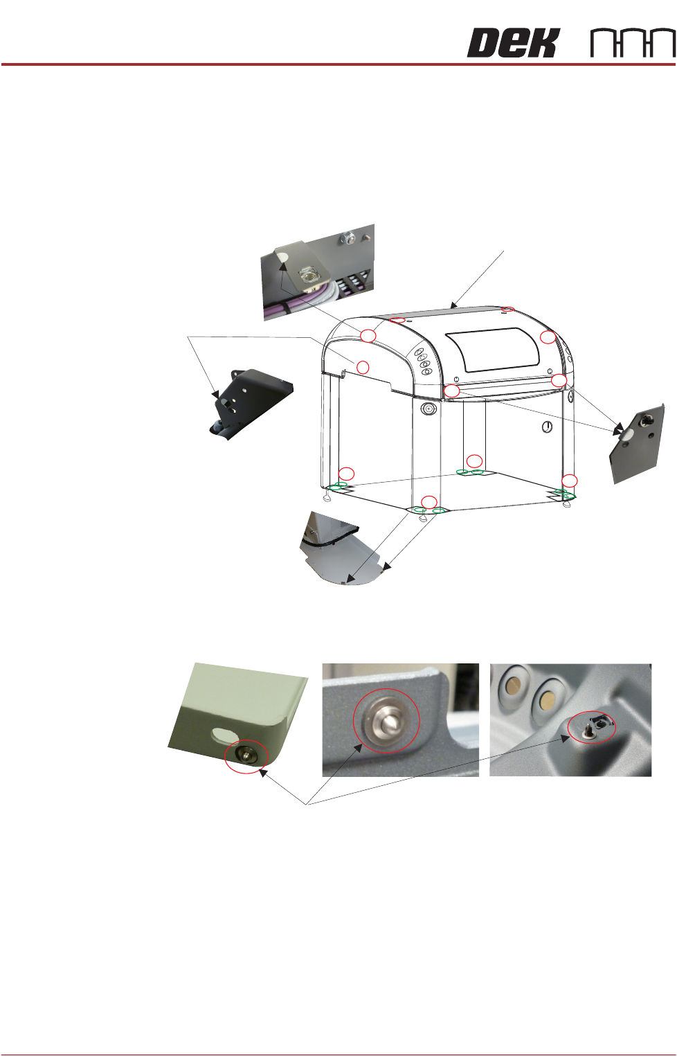
Electrostatic
Protected Area
(EPA)
The EPA cover package option is available for the Type 2 Cover printer only.
Each panel on the printer is coated in a conductive layer and the panels are
electrically connected to the adjacent panel creating the Electrostatic Protected
Area. The panels are electrically grounded ensuring surface static deposition is
kept well below 100 Volts.
Figure 3-11 Contact Points
Figure 3-12 Contact Studs
NOTE
This panel is bonded via
the internal gas struts.
3. Two contact clips
per base plate
1. Left and right hand panel frame mountings
4. Left and right hand
rear panel frame mountings
2. Front panel
frame mountings
2
1
2
1
4
3
3
3
3
Studs are spring loaded
and have a threaded body
Contact Studs
COVERS
PRINTER COVERS
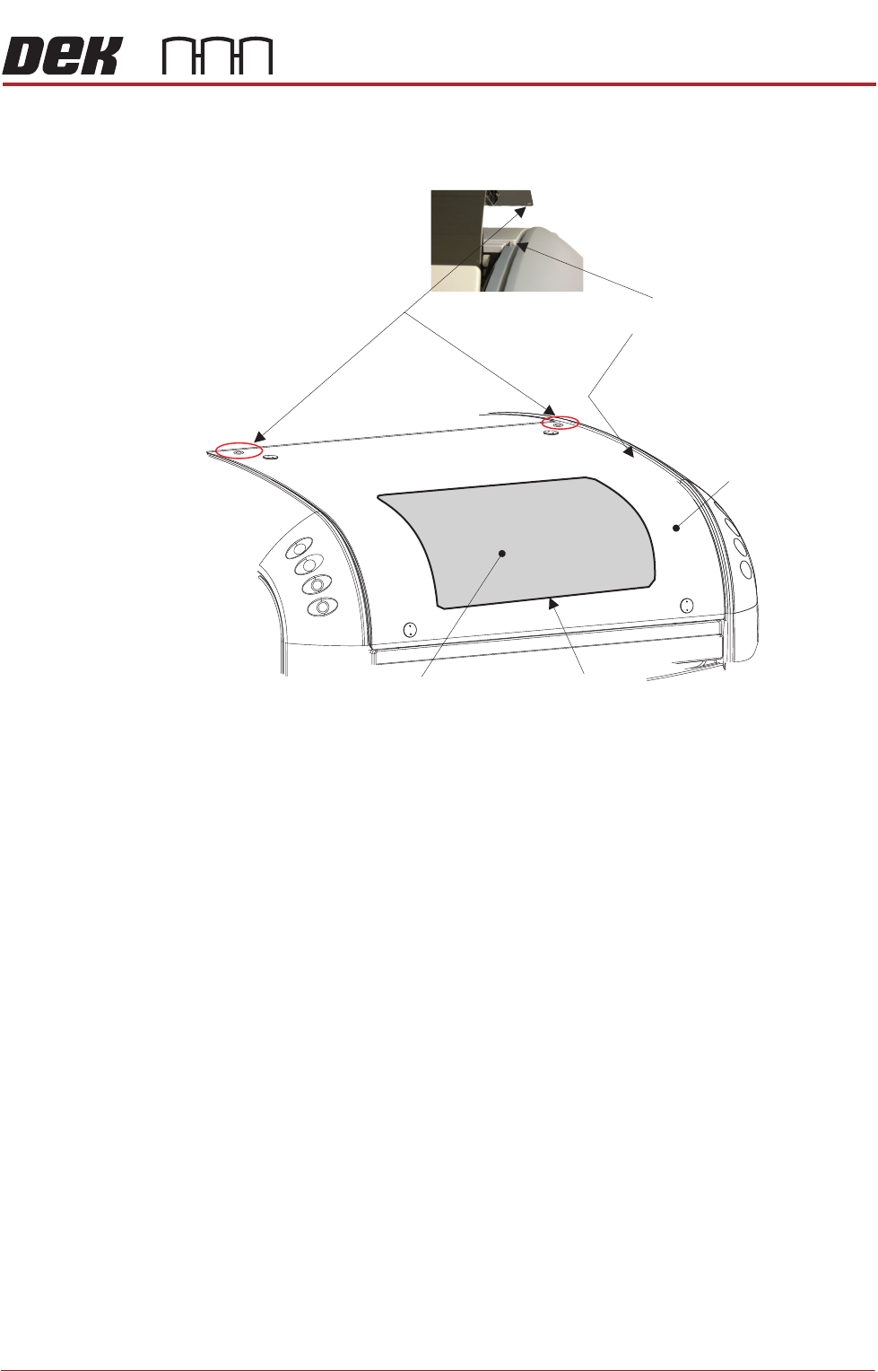
Chapter Issue 11, Jan 17 Technical Reference Manual 3.49
The glass printhead cover is replaced with an aluminium cover with a conduc-
tive Perspex window, fitted with a conductive seal.
Figure 3-13 Printhead Cover
NOTE
For the Electrostatic Protected Area to work effectively, all panels must be fitted
correctly and the printhead cover closed.
Aluminium Cover
Cover Contact Pads
Conductive Perspex Window
Conductive Seal
Studs
(under front cover on upper side panels)