Micron Technical Reference V9 Volume 1.pdf - 第97页
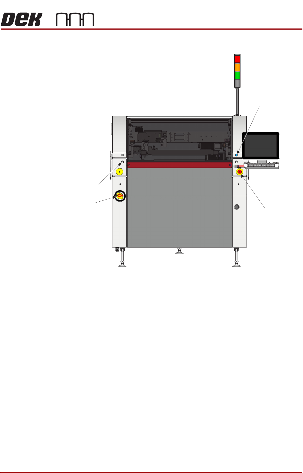
PRINTER OVERVIEW MODULE OVERVIEWS Chapter Issue 11, Jan 17 Technical Reference Manual 4.3 Figure 4-4 T ype 4 Covers View on Front of Machine Left Jog Button E Stop System Button Mains Isolator
PRINTER OVERVIEW
MODULE OVERVIEWS
4.2 Technical Reference Manual Chapter Issue 11, Jan 17
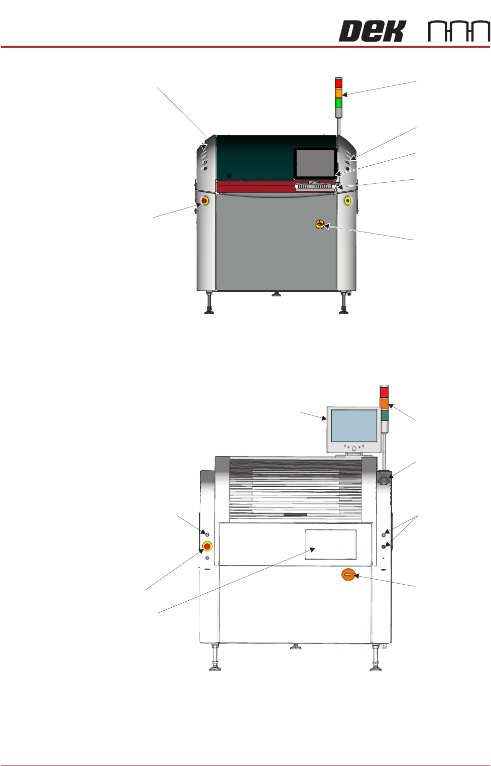
Figure 4-2 Type 2 Covers
Figure 4-3 Type 3 Covers
Beacon
Control Buttons
E Stop
Touch Screen
Monitor
Mains Isolator
Switch
Keyboard/
Trackball Mouse
Control Buttons
Touch Screen Monitor
Control Buttons
Control Button
Mains Isolator
Switch
View on Front of Machine
E Stop
Keyboard
(stowed inside
the cover)
Beacon
Trackball Mouse
PRINTER OVERVIEW
MODULE OVERVIEWS
Chapter Issue 11, Jan 17 Technical Reference Manual 4.3
Figure 4-4 Type 4 Covers
View on Front of Machine
Left Jog Button
E Stop
System Button
Mains
Isolator
PRINTER OVERVIEW
MODULE OVERVIEWS
4.4 Technical Reference Manual Chapter Issue 11, Jan 17
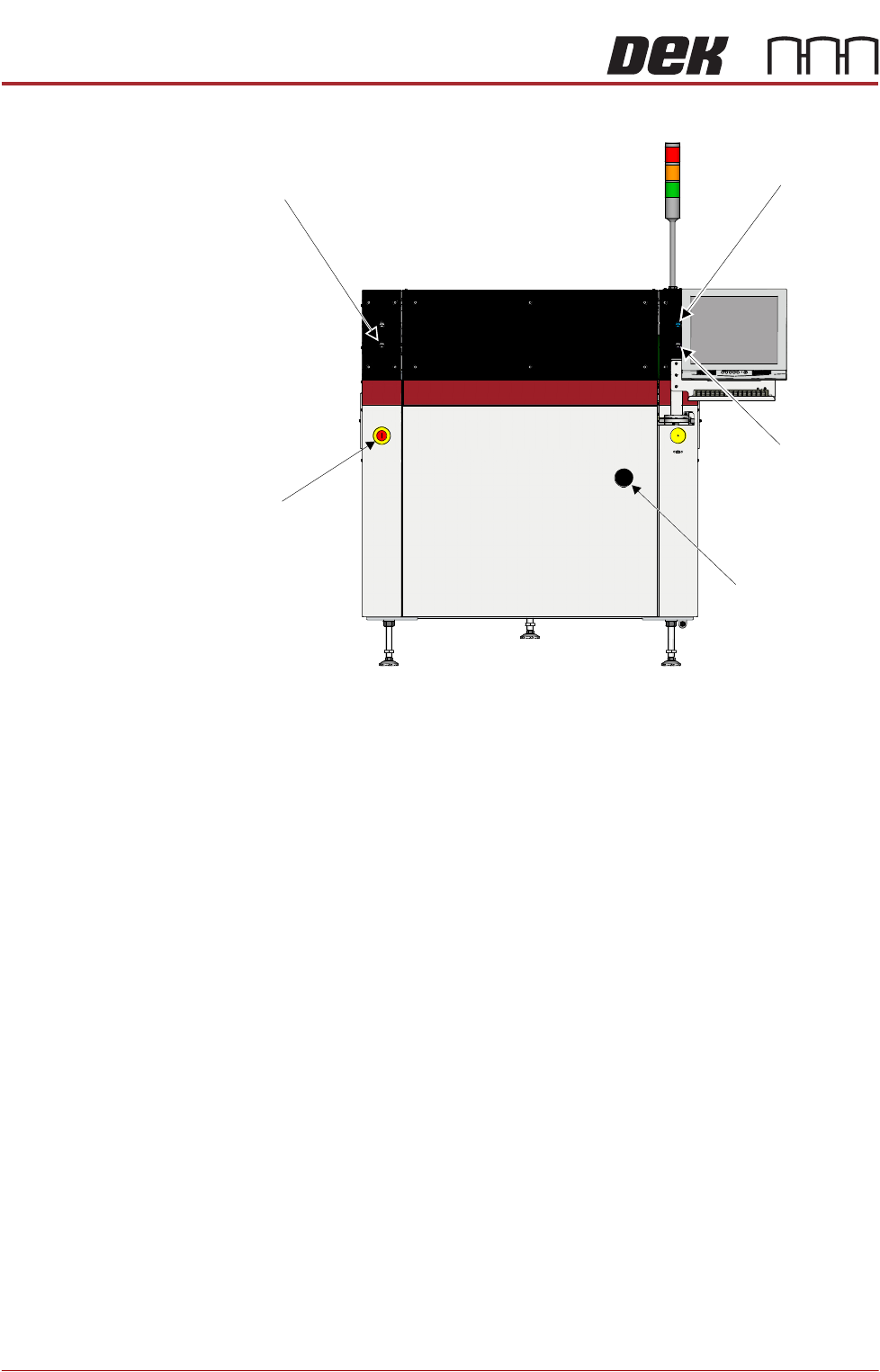
Figure 4-5 Type 5 Covers
Power Supply
Module
The M37 power supply module fulfils the following functions:
• Transform and rectify the mains voltage supply to the voltages required by
the electrical systems throughout the printer.
• Electrical safety - achieved by the use of emergency stop safety circuits (E
Stop). When an E Stop is activated, power is removed from selected areas
of the printer.
Printer Control
Module
The M36 printer control enclosure is the central hub controlling printer motion.
Printer control also consists of I/O Nodes throughout the printer connected to
the printer control enclosure using a CAN Bus.
Printer control is an interface between the software and:
• Stepper Motors
• Servo Motors
• Linear Motors
• Sensors
• Switches
• Solenoids
•Lamps
Left Jog Button
System Button
Right Jog Button
Mains Isolator
E Stop
View on Front of Machine