Micron Technical Reference V9 Volume 1.pdf - 第99页
PRINTER OVERVIEW MODULE OVERVIEWS Chapter Issue 11, Jan 17 Technical Reference Manual 4.5 Printer PC Module The printer PC enclosure is the master controlle r of the printer . Issuing sequen- tial control commands to sla…
PRINTER OVERVIEW
MODULE OVERVIEWS
4.4 Technical Reference Manual Chapter Issue 11, Jan 17
Figure 4-5 Type 5 Covers
Power Supply
Module
The M37 power supply module fulfils the following functions:
• Transform and rectify the mains voltage supply to the voltages required by
the electrical systems throughout the printer.
• Electrical safety - achieved by the use of emergency stop safety circuits (E
Stop). When an E Stop is activated, power is removed from selected areas
of the printer.
Printer Control
Module
The M36 printer control enclosure is the central hub controlling printer motion.
Printer control also consists of I/O Nodes throughout the printer connected to
the printer control enclosure using a CAN Bus.
Printer control is an interface between the software and:
• Stepper Motors
• Servo Motors
• Linear Motors
• Sensors
• Switches
• Solenoids
•Lamps
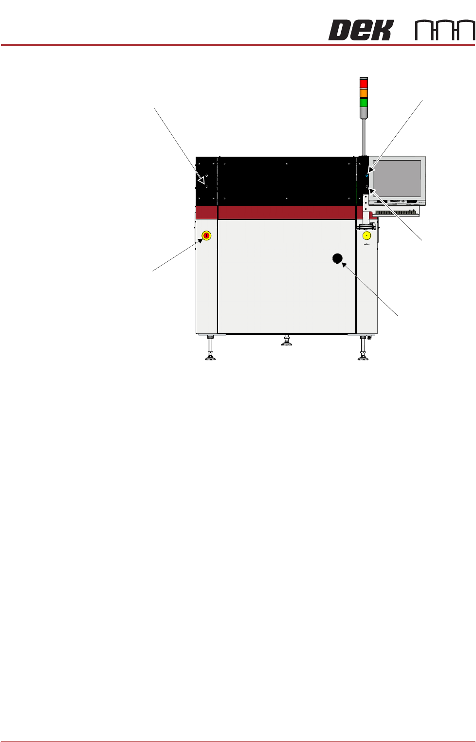
Left Jog Button
System Button
Right Jog Button
Mains Isolator
E Stop
View on Front of Machine
PRINTER OVERVIEW
MODULE OVERVIEWS
Chapter Issue 11, Jan 17 Technical Reference Manual 4.5
Printer PC Module The printer PC enclosure is the master controller of the printer. Issuing sequen-
tial control commands to slave systems via the printer control enclosure, the PC
analyses the feedback signals and issues further commands to ensure the
correct operation and safety of the printer.
NOTE
Type 4 printers Power Supply, Printer Control and Printer PC modules are
positioned and accessed from the front of the printer.
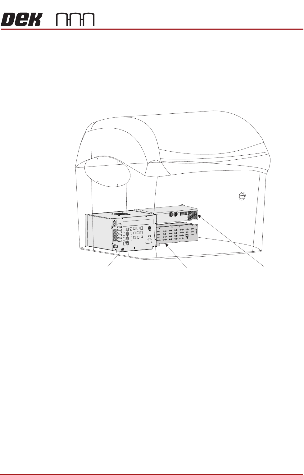
Figure 4-6 Power Supply - Printer Control - Printer IBus PC
Power Supply Module Machine PC EnclosureMachine Control Enclosure
PRINTER OVERVIEW
MODULE OVERVIEWS
4.6 Technical Reference Manual Chapter Issue 11, Jan 17
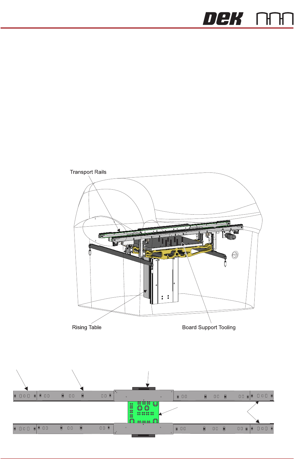
Rising Table
Module
The rising table module provides a stable base for the board support tooling and
positions the transport rails at various heights during the print cycle.
Board Support
Tooling Module
The role of the board support tooling is to support the board during the print
stroke, to prevent print distortion caused by flexing of the board as a result of
the downward pressure of the squeegees/ProFlow. Several different types of
board support tooling are available to suit a variety of surface mount process
requirements.
Transport Rails
Module
The transport rail system is a programmable width conveyor system, utilized to
transport the board through the printer and to secure the board during the print
stroke. The rail system height is positioned by the rising table, during the print
cycle. Two systems are currently available, the RS or rail system and the MTR
or modular transport rail; the latter has a modular centre section which can give
support to a variety of clamping arrangements.
Figure 4-7 Rising Table - Board Support Tooling - Transport Rails (RS)
Figure 4-8 Transport System (MTR)
Board
Transport Belts
Centre Section - Over theTop Snuggers (OTS)
Mid RailEnd Rail
Modular Transport Rails