JANETS_INM.pdf - 第130页
JaNets In structio n Manual 5. Shopflo or Setu p 5- 10 Setting the floor properties When you clic k the <Prop erties> but ton, the f ollow ing screen a ppears. Figure 5.2 - 20 “Floor Pr operties” Figure 5 .2 - 21 B…
JaNets Instruction Manual 5. Shopfloor Setup
5-9
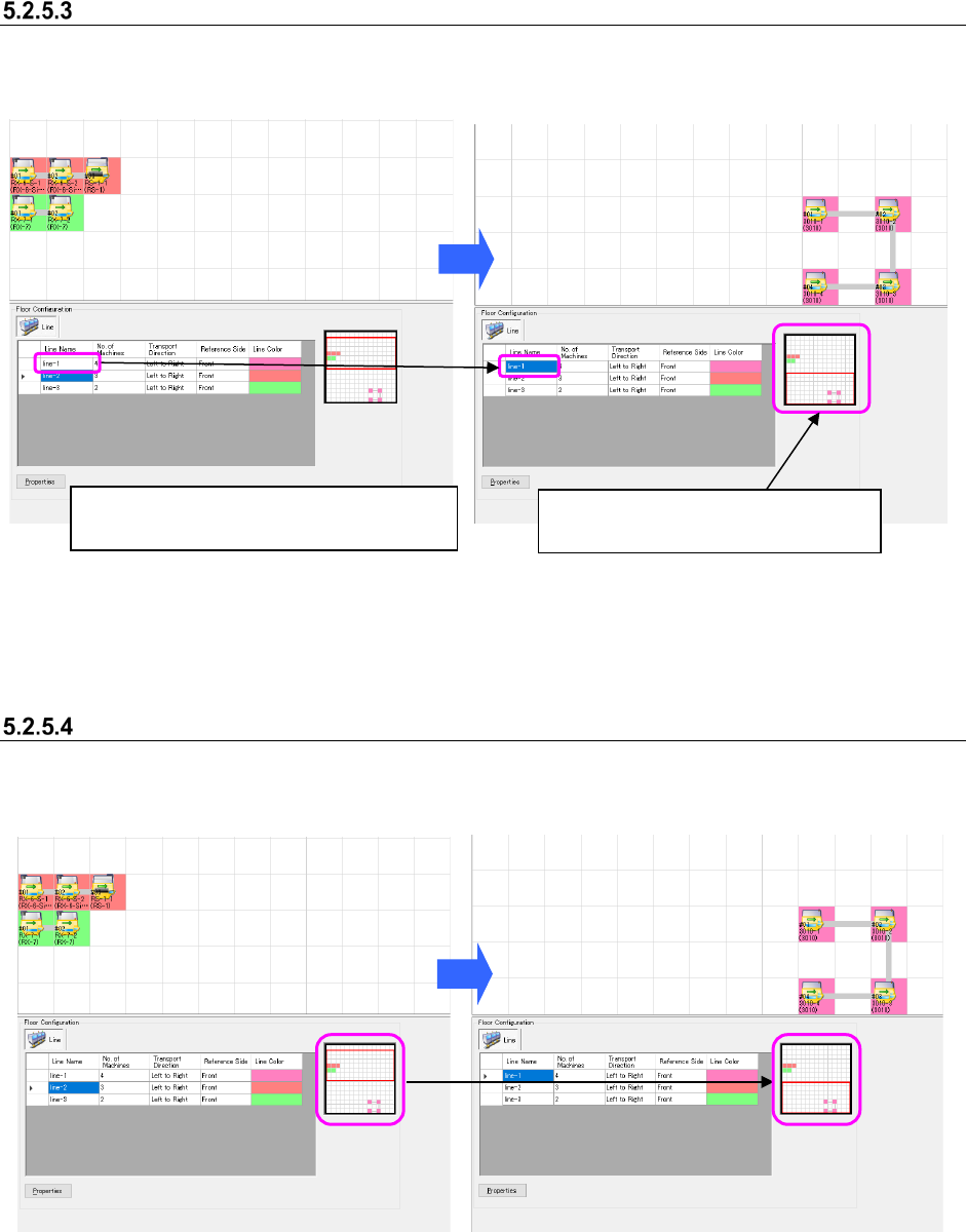
Searching the display position
When you select the desired line from the floor details list, the floor view is moved to the assigned
position.
Figure 5.2-16 Production line view – Before a
production line is searched
Figure 5.2-17 Production line view – After a
production line is searched
Moving the floor map display area
Drag the display area cursor on the floor map and move the mouse. The display area is moved
onto the floor view.
Figure 5.2-18 Before the display area cursor
is moved on the floor map
Figure 5.2-19 After the display area cursor is
moved on the floor map
Select the production line “LINE-1” from the
“production line list.”
The floor view is moved to the
assignment position of the “LINE-1.”
JaNets Instruction Manual 5. Shopfloor Setup
5-10
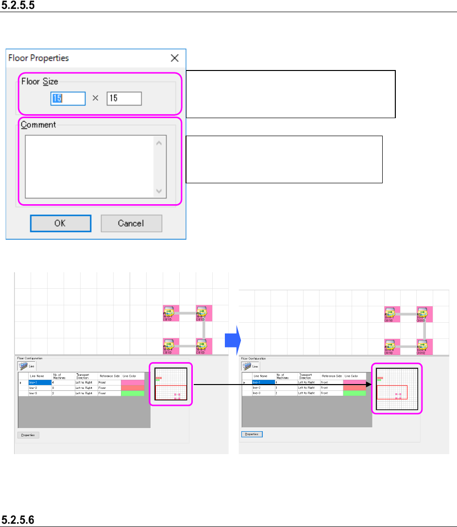
Setting the floor properties
When you click the <Properties> button, the following screen appears.
Figure 5.2-20 “Floor Properties”
Figure 5.2-21 Before changing the settings in
the “Floor Properties” fields
Figure 5.2-22 After changing the settings in
the “Floor Properties” fields
When an error message appears
An error message appears when:
1. You change the setting in the “Floor Properties” fields to any value not within the input range.
2. You set the floor size smaller than the production line assignment area on the floor view.
* When you click the <OK> on the error message screen in either case above, the
“Shopfloor Setup” screen reappears.
Set the “Floor Size” in the following format:
horizontal width (X-axis) × vertical width (Y-axis).
Input range: 5×5 to 50 × 50
Set the comment for a floor.
You can enter up to 64 characters regardless
of the character width, half-width or full-width.
JaNets Instruction Manual 5. Shopfloor Setup
5-11
Line – How to Operate
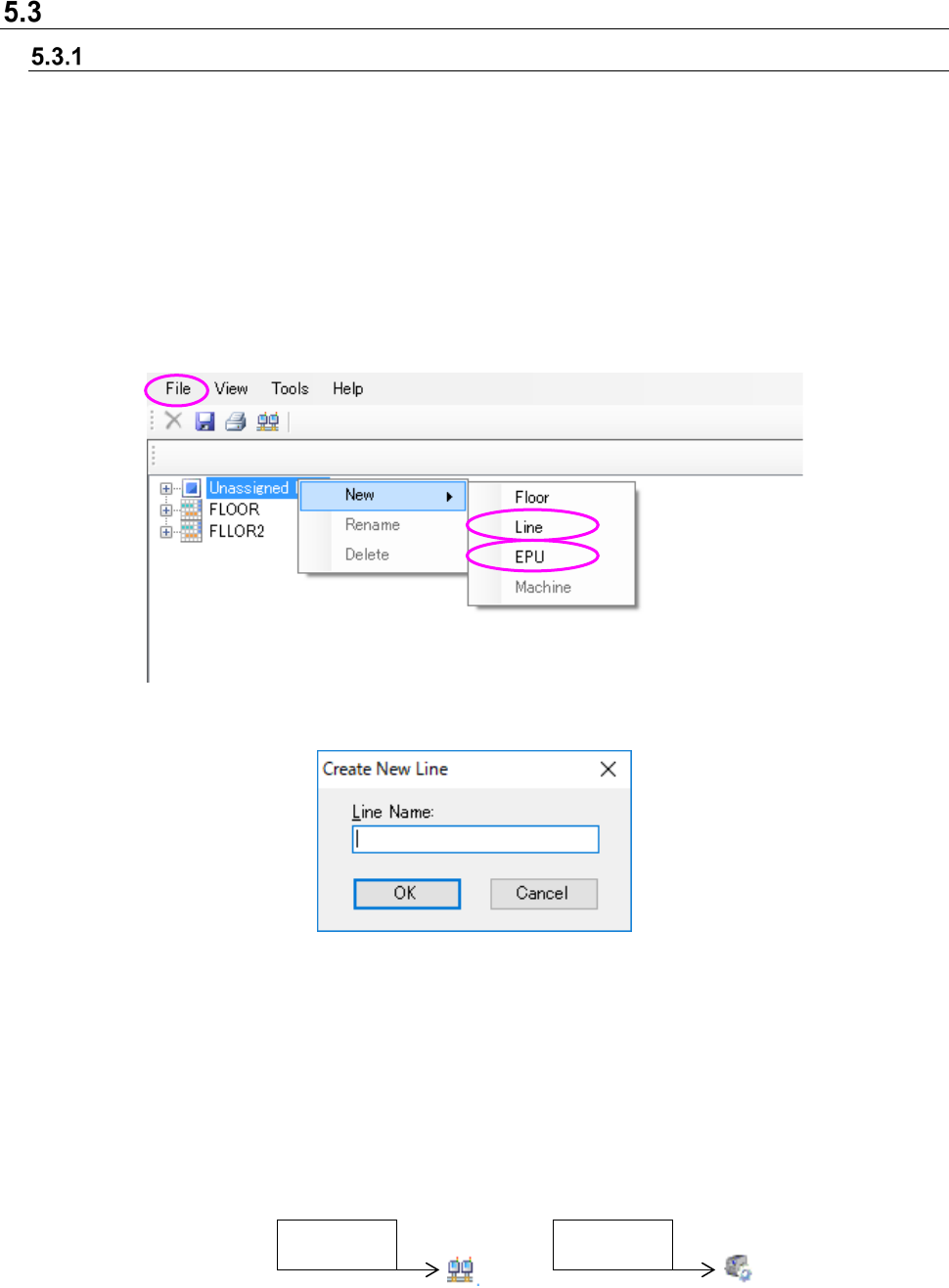
Creating a new production line
Select an unassigned production line or a floor from the floor configurations tree, and then perform
the operation ① or ② below.
To create a line configuration of the line mode, select Line. To create a line configuration of the
EPU mode, select EPU.
Line can be selected only when a Line Manager option is added.
① Select the [File] command from the menu bar, the [New] command and the [Line] (or [EPU])
command in this order.
② Click the right button of a mouse to display the pop-up menu. Select the [New] command, and
then the [Line] (or [EPU]) command from this pop-up menu.
Figure 5.3-1 Creating a new production line (Operation ②)
Figure 5.3-2 “Create New Line” dialog box
Line Name: You can enter up to 20 characters, and the lower cases are not distinguished from
the upper cases. You can enter half-width alphanumeric characters and the
following special characters.
However, you cannot use the following special characters: (”)「#」「&」「’」「<」「>」)
You cannot enter same line name between floor and machine, equipment.
OK: The system adds a production line.
Figure 5.3-3 Configuration tree icon
LINE mode
EPU mode