JANETS_INM.pdf - 第184页
JaNets In structio n Manual 5. Shopflo or Setu p 5- 64 Feeder b ank u nit ( examp le of t he layo ut s creen) Y ou can set a feeder on each att achment positio n of the bank as y ou like ( * ). When you set a f eeder , t…
JaNets Instruction Manual 5. Shopfloor Setup
5-63
Display of a feeder type
Information on a feeder set as a permanently feeder is displayed here.
Figure 5.9-5 Display of a feeder type
Figure 5.9-6 Display of the component data
(example for indicating that an feeder cannot be set)
Figure 5.9-7 Display of the
component data (tray items)
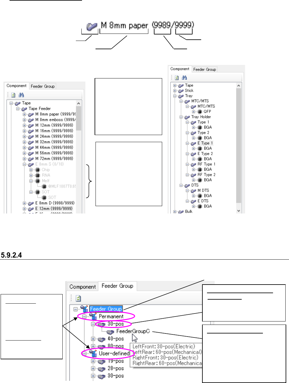
“Feeder Group” list (tree screen)
The list of created permanent feeder groups is displayed in the tree format.
Figure 5.9-8 “Feeder Group” list
* Only feeder group types (number of holes on the bank) and feeder group names of the feeder
group information that is set in the feeder set database are displayed on this screen.
Feeder type (M: mechanical, E: electric)
Icon
Number of feeders that can be set
Number of feeder resources
When the number of
feeders of a type that
can be set reaches “0,”
the corresponding icon
is displayed in gray
(that is, you cannot set
this type of feeders any
more).
When the number of
feeders that can be set
becomes 1 or more by
clearing a feeder(s) set
as a permanent feeder,
you can set that type of
feeder(s).
Feeder group type (bank
information): Classified
according to the number of
holes on the (left) front bank
for a feeder group.
Feeder group name:
A feeder group created on
the “Permanent Feeder
Setup” screen is displayed
here. When you put the
mouse pointer on it,
information of all the banks is
displayed on a tooltip.
Root
Permanent:
Feeder group set
as the permanent
information of a
machine
User-defined:
Feeder group not
set in a machine
JaNets Instruction Manual 5. Shopfloor Setup
5-64
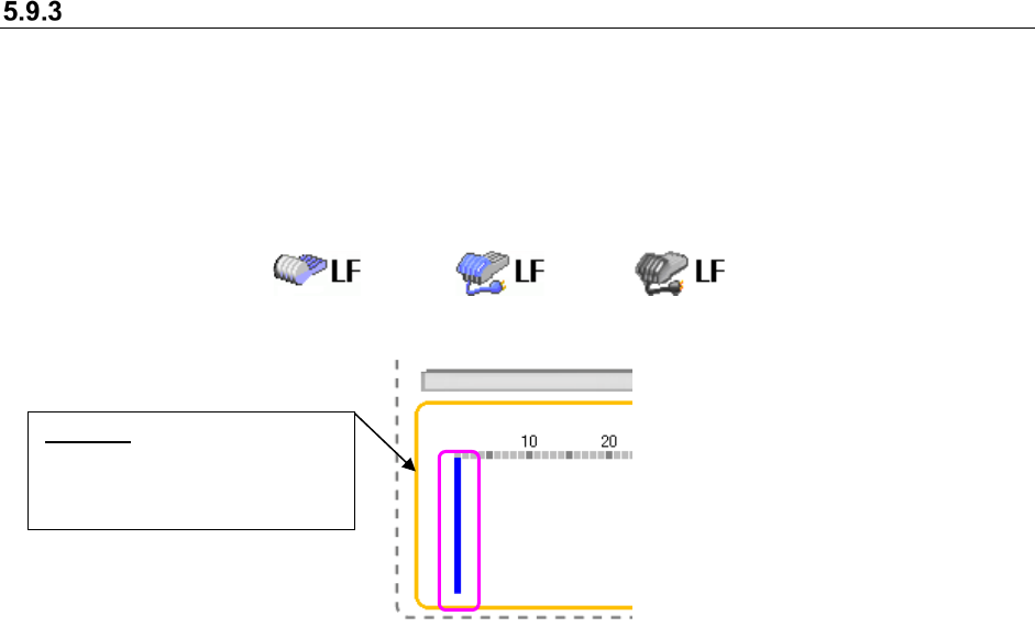
Feeder bank unit (example of the layout screen)
You can set a feeder on each attachment position of the bank as you like (*).
When you set a feeder, the image of the feeder is displayed in corresponding size.
* Feeder types that can be attached on each position vary depending on machine models.
The icon that represents a driving method of bank, the mechanical type or the electric type, is
displayed for all types of machines.
Figure 5.9-9 Icons representing the driving method of bank
(Left side: Mechanical type, Center side :Electric type(EF)/Right side :Electric type(RF))
Figure 5.9-10 Selecting a position (No feeder is set yet.)
To change the position of the blue bar, click the desired position on the layout screen with the
mouse; the blue bar moves to the new position.
Besides the mouse, the arrow keys on the keyboard also work to change the position of the blue
bar. With the <Down> or <Right> arrow key, the blue bar moves in ascending order. With the <Up>
or <Left> arrow key, it moves in descending order. Refer to the following example:
Blue bar: Indicates a position
that you selected; no feeder is
set to this position yet in this
state.
JaNets Instruction Manual 5. Shopfloor Setup
5-65
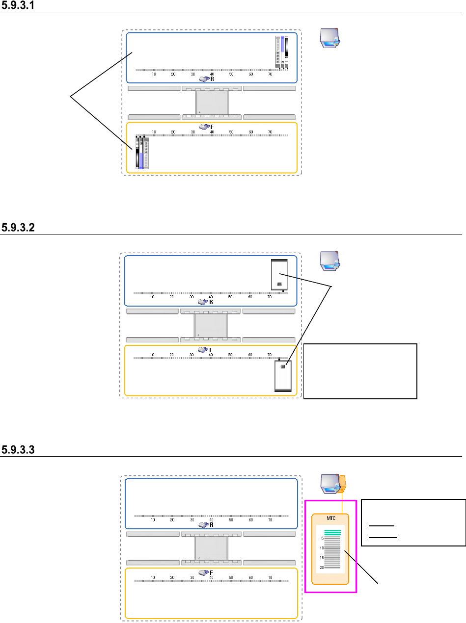
Machine having two banks on each of which 80 holes are located
Figure 5.9-11 Feeder bank unit (two banks on each of which 80 holes are located)
When an IC collection belt is set
Figure 5.9-12 Feeder bank unit (when IC collection belts are set)
When an MTC is set
Figure 5.9-13 Feeder bank unit (when an MTC is set)
Banks
IC collection belts
You can set a feeder at
any position other than
the position an IC
collection belt occupies.
Where MTC/MTS
feeder is attached
<Color of a tray base>
Gray: Not set base
Green: Set base