JANETS_INM.pdf - 第185页
JaNets In structio n Manual 5. Shopflo or Setu p 5- 65 Machine having two banks on each of which 8 0 holes are located Figure 5.9 - 11 Feeder bank unit (two banks on each of which 80 hol es are located) When an IC collec…
JaNets Instruction Manual 5. Shopfloor Setup
5-64
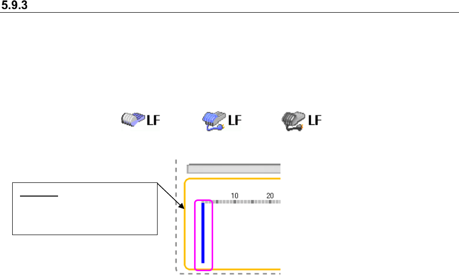
Feeder bank unit (example of the layout screen)
You can set a feeder on each attachment position of the bank as you like (*).
When you set a feeder, the image of the feeder is displayed in corresponding size.
* Feeder types that can be attached on each position vary depending on machine models.
The icon that represents a driving method of bank, the mechanical type or the electric type, is
displayed for all types of machines.
Figure 5.9-9 Icons representing the driving method of bank
(Left side: Mechanical type, Center side :Electric type(EF)/Right side :Electric type(RF))
Figure 5.9-10 Selecting a position (No feeder is set yet.)
To change the position of the blue bar, click the desired position on the layout screen with the
mouse; the blue bar moves to the new position.
Besides the mouse, the arrow keys on the keyboard also work to change the position of the blue
bar. With the <Down> or <Right> arrow key, the blue bar moves in ascending order. With the <Up>
or <Left> arrow key, it moves in descending order. Refer to the following example:
Blue bar: Indicates a position
that you selected; no feeder is
set to this position yet in this
state.
JaNets Instruction Manual 5. Shopfloor Setup
5-65
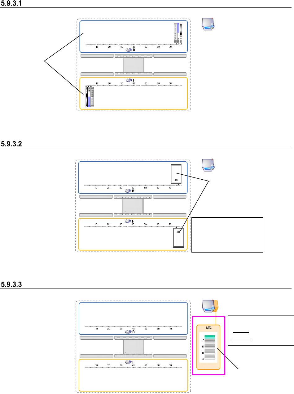
Machine having two banks on each of which 80 holes are located
Figure 5.9-11 Feeder bank unit (two banks on each of which 80 holes are located)
When an IC collection belt is set
Figure 5.9-12 Feeder bank unit (when IC collection belts are set)
When an MTC is set
Figure 5.9-13 Feeder bank unit (when an MTC is set)
Banks
IC collection belts
You can set a feeder at
any position other than
the position an IC
collection belt occupies.
Where MTC/MTS
feeder is attached
<Color of a tray base>
Gray: Not set base
Green: Set base
JaNets Instruction Manual 5. Shopfloor Setup
5-66
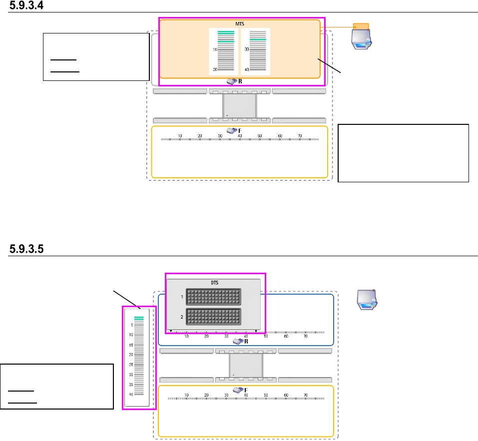
When an MTS is set
Figure 5.9-14 Feeder bank unit (when an MTS is set)
When a DTS is set
Figure 5.9-15 Feeder bank unit (when a DTS is set)
The position on which an MTS
tray is attached is displayed on
the R (rear) bank.
<Color of a tray base>
Gray: Not set base
Green: Set base
Tray assignment
screen
<Color of a tray feeder>
Gray: Not set tray
Green: Set tray
You can set a feeder type
that can be attached for each
machine model on only the F
(front) bank.