JANETS_INM.pdf - 第202页
JaNets In structio n Manual 5. Shopflo or Setu p 5- 82 Feeder L ayou t Scr een V ario us types of feed ers a nd/or tr ays whose c omponent s upply pos ition is sp ecified are d isplayed here. Whe n “Auto” is sel ect ed i…
JaNets Instruction Manual 5. Shopfloor Setup
5-81
Operations
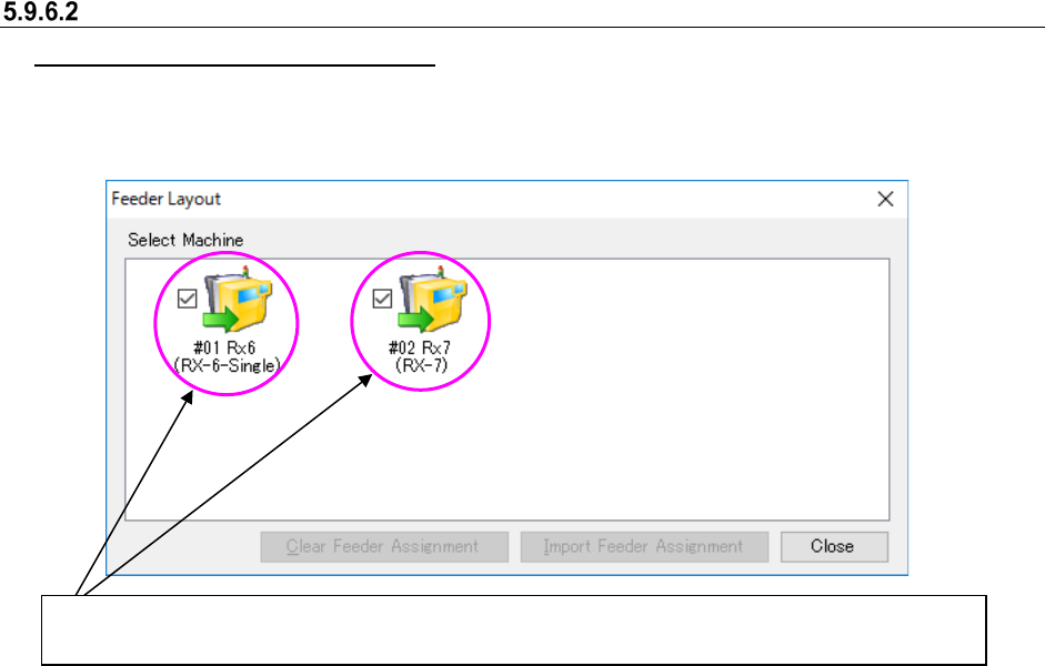
Selecting a machine to be displayed
When you select a Machine selection button, the feeder layout screen of the corresponding
machine can be displayed.
Figure 5.9-51 When two or more machines are selected on the “Select Machine” dialog box
Two or more feeder layout screens can be displayed at the same time. The check box of the Machine
selection button whose corresponding feeder layout screen is displayed is checked on the screen.
JaNets Instruction Manual 5. Shopfloor Setup
5-82
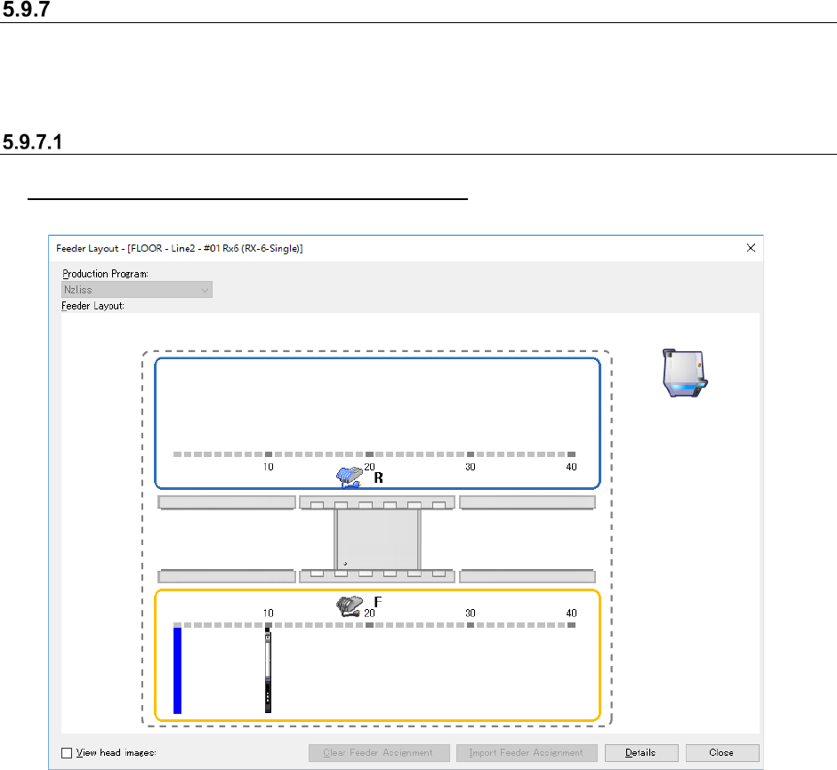
Feeder Layout Screen
Various types of feeders and/or trays whose component supply position is specified are displayed
here. When “Auto” is selected in the “Machine” or “Bank” field, the corresponding data is not
displayed on the screen.
Configuration of the “Feeder Layout” screen
When only a production program is to be referred
Figure 5.9-52 “Feeder Layout” screen
JaNets Instruction Manual 5. Shopfloor Setup
5-83
Color of an assigned feeder
A feeder assigned on the layout screen is colored depending on its condition as shown below.
Figure 5.9-53 Colors of a feeder icon (normal condition, selected, set as a permanent feeder.)
* When the condition of each lane is different from that of a feeder itself if it has two or more
lanes, each lane and the feeder are colored depending on its condition respectively.
Operations(Feeder layout screen)
Displaying the details of a feeder
When you move the cursor over a feeder, the following items are displayed. When you move the
cursor over a permanent feeder, “[Permanent]” is additionally displayed at the component supply
position. When a feeder has two or more lanes, the lane number is displayed also. When you
move the cursor over a DTS, the tray level number from which components are supplied is
displayed.
Figure 5.9-54 Example of the “Feeder Layout” window (as a pop-up window)
Editing on the “Feeder Layout” screen
When you select the <Close> button on the “Select Machine” dialog box after editing data, the
message asking you whether to reflect your editing in the program data appears on the screen.
When you select the <Yes> button, your editing is reflected in the program data. At this time, the
Pick data is updated. The moved or copied component pick-up coordinates on a feeder are reset
to the designed values. The editing functions are explained below. Note that you cannot edit any
data on an IC collection belt.
Selecting a feeder
You can move, copy or delete a feeder by moving the cursor over the feeder or by dragging
the mouse to surround the feeder.
Normal condition:
black
Selected:
orange
Set as a permanent
feeder: blue
Each item is displayed also for a “stick,” “tray” or
“bulk” feeder or an “IC collection belt.”