JANETS_INM.pdf - 第208页
JaNets In structio n Manual 7. Program Editor 7-1 7. Progr am E ditor 7.1 Intr oduction The Progra m Editor allows y ou to creat e a producti on program for a machi ne of the se lected production line. 7.2 Star ting Up o…

JaNets Instruction Manual 6. Language Changer
6-2
6.1.2 Switching the language
When you select the “Language” combo box, the list of selectable languages is displayed
on the pull-down list.
Figure 6.1-3 List of selectable languages
Select the language you want to switch to on the list, and then click the <Change> button.
The language that is being used in all running MI Line Optimizer application programs is
switched to the selected one.
Figure 6.1-4 “JaNets Launcher” screen before/after the used language is switched
Displayed in Japanese
Displayed in English
JaNets Instruction Manual 7. Program Editor
7-1
7. Program Editor
7.1 Introduction
The Program Editor allows you to create a production program for a machine of the selected
production line.
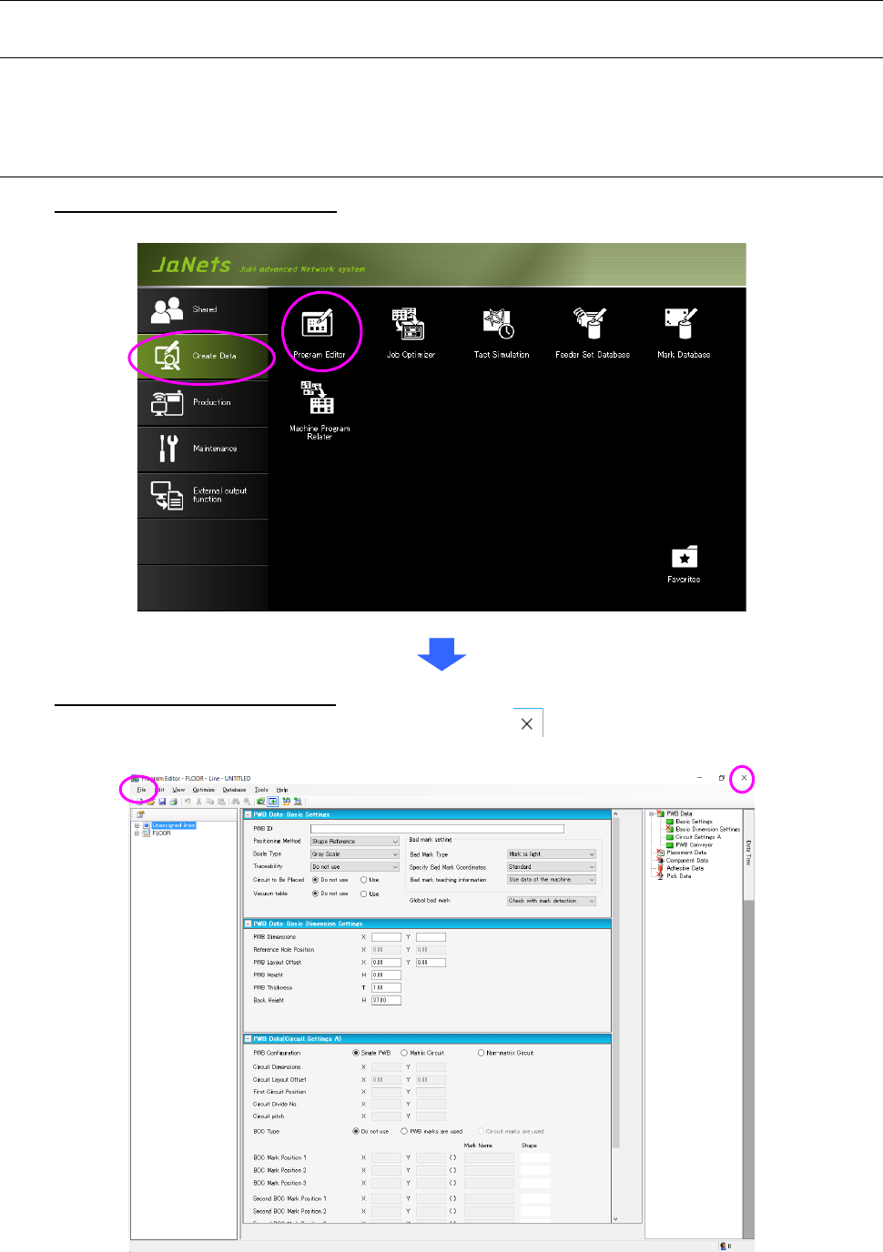
7.2 Starting Up or Quitting the Program Editor
To start up the Program Editor: Double-click the “Create Data” tab from the JaNets Launcher,
and then the “Program Editor” icon.
To quit the Language Changer: Click the “File” tab, and then the “Program Editor” icon, or
select the close ( ) button at the upper right corner of the
title bar.
Figure 7.2-1 Screen displayed when the Program Editor starts up for the first time
JaNets Instruction Manual 7. Program Editor
7-2
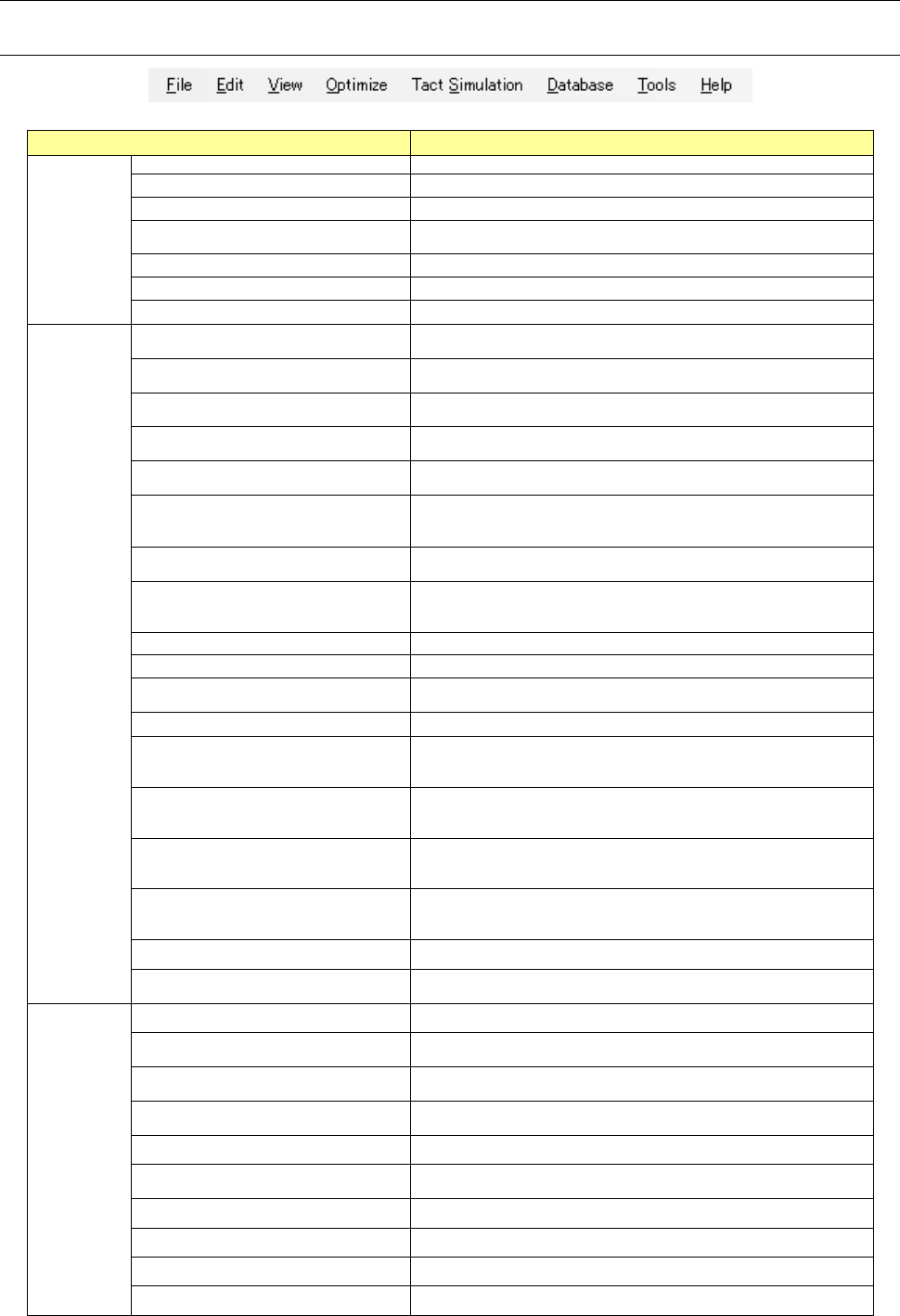
7.3 Menu Configuration
7.3.1 Menus
Table 7.3-1 Description of each menu item
Menu item Description
File (F)
New (N)
Creates a new production program.
Open (O)
Opens a production program.
Save (S)
Saves a production program that is being edited.
Save as (A)
Assigns a name to a production program that is being edited, and
saves it.
Read CAD Data (C)
Reads CAD data into a production program.
Print & Save to file (P)
Prints production program data and outputs it as a file (*).
Exit Program Editor (X)
Quits the Program Editor.
Edit (E)
Undo (U)
Cancels the operation you have done most recently, and restores
the data to its original state.
Cut (T) <on the “Placement Data”
screen or “Pick Data” screen>
Saves data temporarily in a clipboard.
Copy (C) <on the “Placement Data”
screen>
Copies data onto the clipboard.
Paste (P) <on the “Placement Data”
screen>
Pastes data on the clipboard by the number of times specified for
copy operation.
Insert Line (I) <on the “Placement Data”
screen>
Inserts a blank line.
Duplicate Line (D) <on the “Placement
Data” screen or the “Pick Data”
screen>
Duplicates the specified line.
Location (G) ... <on a screen other than
the “PWB Data” screen>
Moves the cursor to the specified line.
Search (S) ...<on the “Placement
Data” screen, the “Component Data”
screen or the “Pick Data” screen>
Searches a placement ID or a component name, and displays the
screen for setting the search function.
Find Next (N) ...
Searches the next data.
Replace (R)
Replaces the component data at a time (*).
Cell Copy (O) <on the “Placement
Data” screen>
Copies data in a cell onto the clipboard.
Cell Paste (A)
Pastes data on the clipboard into a cell.
Change Component Name (H)
Changes a component name, and displays the screen for changing
a component name (you can use this command on a screen other
than the “PWB Data” screen).
Change of adhesive parameter name
(B)
Change of the adhesive pattern name
Display of the adhesive pattern name change screen
<It can be used on the adhesive data screen.>
Update Layers (Y) <on the “Placement
Data” screen or the “Component Data”
screen)
Reflect the component layer in the placement layer: all compo-
nents are selected on the “Placement Data” screen, while a com-
ponent is selected on the “component Data” screen.
Matrix Paste (M) ...
Expands coordinates in a matrix according to your input of the X
pitch, Y pitch and the number of times, and then paste them. The
number of placement data records should be up to 30,000.
Clear Unlinked Comp Info (L) Deletes component data not linked with any placement data.
Clearing of unlinked adhesive infor-
mation (R)
Deletion of the adhesive data that is not linked with the component
data.
View (V)
Data Completion Status (D) Displays each data completion status.
Divided Placement Data (P) ...
Displays placement data that is assigned to each machine with the
Optimize function.
Feeder Layout (F) ...
Displays the feeder assignment condition of each machine graph-
ically.
Nozzle Layout (N) ...
Displays nozzles that are assigned to each machine with the Opti-
mize function.
Status (S) ... Displays the result of the tact (cycle time) simulation (*).
Board Viewer (V)
Displays the board transporting direction, the board layout offset,
the positioning hole and the component layout graphically.
Guidance Displays the explanation of an object where the cursor is located.
Coherence Check Results Displays the results of the data coherence check.
Line Explorer (E) ... Displays/hides the Line Explorer.
Toolbar (T) Displays/hides the toolbar.