JANETS_INM.pdf - 第214页
JaNets In structio n Manual 7. Program Editor 7-7 Editing PWB Data (Circuit Settings) When you select t he “ PWB Da ta ” fro m the tree v iew , and t hen the “ Circuit Settings A, ” the fol lowin g screen appe ars. Figur…
JaNets Instruction Manual 7. Program Editor
7-6
Editing PWB Data (Basic Dimension Settings)
When you select the “PWB Data” from the tree view, and then the “Basic Dimension Settings,” the
following screen appears.
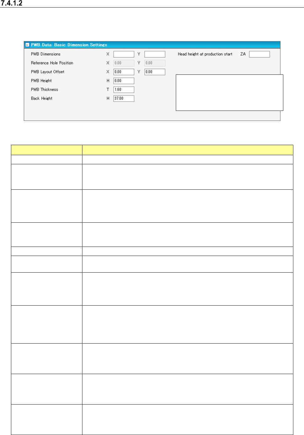
Figure 7.4-3 PWB data (PWB Dimension Settings) screen
Table 7.4-2 PWB data (PWB Dimension Settings) screen
Item Description
PWB Dimensions
Set up the outer dimensions of a PWB.
Reference Hole Position Set up the positioning hole position seen from a PWB position reference.
This item can be set up only when "Reference Hole Position” is selected as the
method of positioning a PWB.
PWB Layout Offset
Set up the coordinates of the PWB layout edge point seen from a PWB position
reference.
A PWB layout edge point changes depending on a transport direction and a ref-
erence surface.
PWB Height Set up the height of PWB surface seen from the transport reference surface.
[When a JX-350 is used]
“0” (zero) is always displayed regardless of what value you entered.
PWB Thickness
Set up the thickness of a PWB.
Back Height
Set up the distance including the component height to the back side of a PWB
seen from a transport reference surface.
Clamp offset
Set up the clamp offset which detects a PWB edge point with an HMS at the time
of the second clamp of a large-sized board.
Whenever the PWB outer dimensions Y changes, default of the clamp offset is set
up.
Head height at production
start
This item is displayed when an RS-1 and JM-100 included in the production line.
Enter the maximum height of a component already placed on a board with the
previous process of the JaNets.
Since a blank is displayed for this item by default, the PWB data cannot be created
completely unless you enter this item.
Every clamp place range
X1
This item is displayed when a JX-350 is used.
If the X-dimension of the board outer dimensions “PWB Dimensions” exceeds 650
mm, enter the range in which a component is placed when the board is clamped
for the first time.
Every clamp place range
X2
This item is displayed when a JX-350 is used.
If the X-dimension of the board outer dimensions “PWB Dimensions” exceeds
1200 mm, enter the range in which a component is placed when the board is
clamped for the second time.
PWB Place height
This item is displayed when a JX-350 is used.
You cannot edit this setting.
A value calculated based on the board height set in the “PWB Height” field and the
board thickness set in the “PWB Thickness” is displayed here.
* The unit of the length displayed here
is specified with the Shopfloor Setup
application, and you can set the
length in mm or inch.
JaNets Instruction Manual 7. Program Editor
7-7
Editing PWB Data (Circuit Settings)
When you select the “PWB Data” from the tree view, and then the “Circuit Settings A,” the following
screen appears.
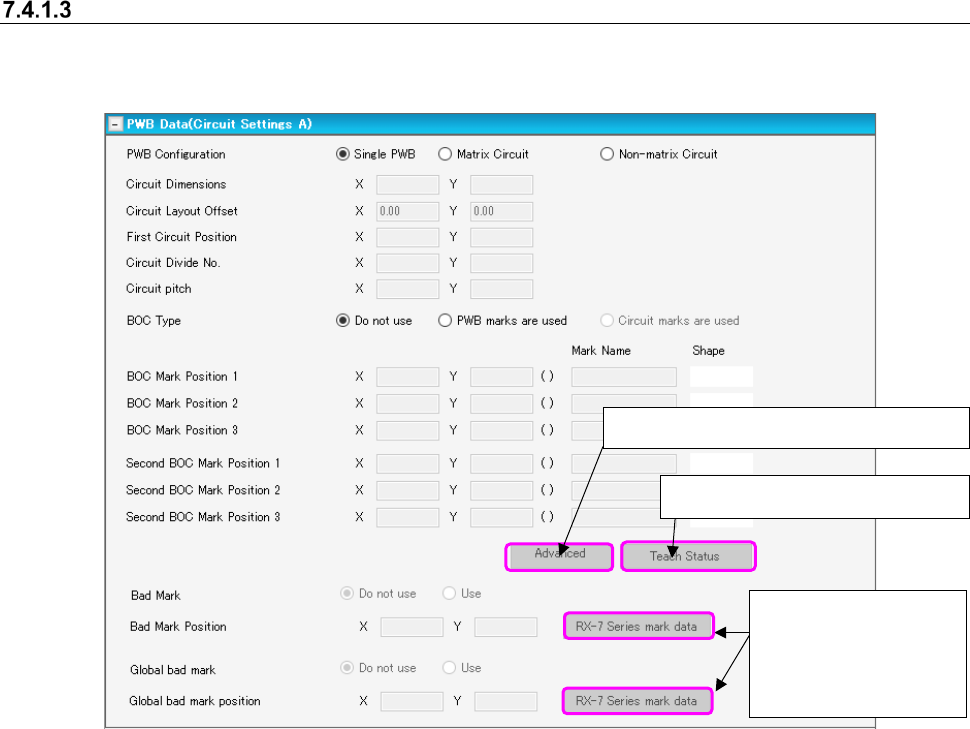
Figure 7.4-4 PWB data (Circuit A settings) screen
When you press the <Advanced> button, the BOC mark information for each machine can be
displayed or set.
Only RX-6/RX-7/RS-1/JM-100 can set the BOC mark.
The <Advanced> button is enabled only when two or more BOC mark positions are set or two or
more second BOC mark positions are set.
[When a JX-350 is used]
The area in which you are supposed to enter information on the third BOC mark is displayed.
It is displayed on the “Advanced settings” screen and the “Teach Status” screen also.
[In Case of the Line only for JM-10 and JM-20]
None of the menu item “Global bad mark,” the <Advanced> button and the <RX-7 series mark
data> button are displayed on the screen.
[In Case of the Line including JM-100]
RX-7 series Bad Mark Information becomes non-display.
Displays the “Teach Status” dialog.
Displays “Advanced settings” dialog.
Displays the dialog box
for setting bad mark
data to be used with an
RX-7 series.
JaNets Instruction Manual 7. Program Editor
7-8
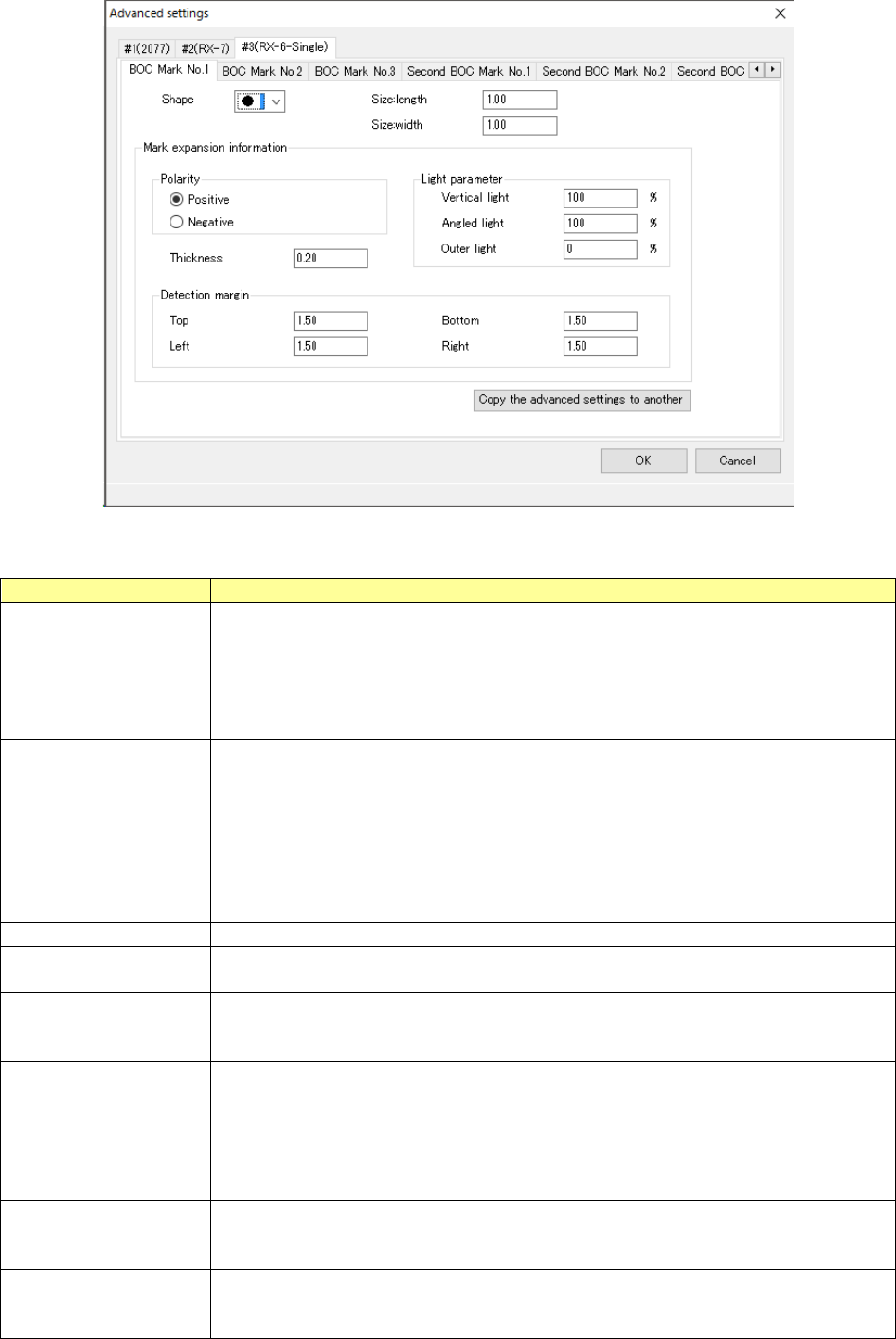
Figure 7.4-5 Detail setting screen
Table 7.4-3 Detail setting items
Item
Contents
Machine name tab
Displays the tabs of the machine of the currently selected line, and performs BOC mark
setting for each machine.
#1 (RX-7), #2 (RX-7) ----
Only RX-6/RX-7 can edit BOC marks.
The other machine or user template mark can display them but cannot edit them.
(Each item in the BOC mark setting is indicated in gray and cannot be edited.)
BOC mark No. tab
The tabs of BOC mark No.1 ~ 3 and second BOC mark No.1 ~ 3 are displayed and the
set value of each BOC mark is displayed. However, the BOC mark or second BOC
mark for which the coordinate position XY is not set in the “PWB data (circuit setting A)”
panel are displayed but cannot be edited.
When the specified BOC mark is already taught, (*) is indicated for the tab.
Example: BOC mark No.1 (*)
If the mark information in the tab is changed, the teaching information (*) of the tab is
cancelled.
Shape
Sets the mark shape from the combo box.
Vertical size and hori-
zontal size
Sets the mark size.
The input range is 0.5 mm to 3.00 mm.
Polarity
Sets how to image the mark for the PWB.
Select Positive (PWB = dark, mark = bright) or Negative (PWB = bright, mark = dark).
Default: Positive
Line width
Sets the line width of the skin shape.
Input range: 0.20 mm ~ half value of mark size
Default: 0.20 mm
Detection margin (up)
Sets the upper width to detect a mark.
Input range: 0.01 mm ~ (Visual filed – Mark size)/2
Default: 1.50 mm
Detection margin (down)
Sets the upper width to detect a mark.
Input range: 0.01 mm ~ (Visual filed – Mark size)/2
Default: 1.50 mm
Detection margin (left)
Sets the upper width for mark detection.
Input range: 0.01 mm ~ (Visual field – Mark size)/2
Default: 1.50 mm