JANETS_INM.pdf - 第221页
JaNets In structio n Manual 7. Program Editor 7- 14 Editing PWB Data (Circuit Lay out ) When you se lect the “ PWB Da t a ” fro m the tree view , and then the “ Circu it Layout A ” or “ Circ uit Layout B, ” the follow in…
JaNets Instruction Manual 7. Program Editor
7-13
Item
Contents
Mark type
Height
Set the mark height.
The input range is0.00 to999.99.
The thickness / inside
diameter
Set the thickness of the line of the mark. .
You can set this item only when you select a linear shape.
When the mark shape is ◎, enter the diameter of the inner circle.
The input range is0.00 to999.99.
Allowable size range
Set the allowable range of the size of a found mark for the mark size speci-
fied above.
You can set this item only when you select “Shape” for the menu item
“Recognizing.”
The input range is1 to99.
Accept.
Set a threshold value of the image gradation to be used for black-and-white
judgment when you select “Illumination” for the menu item “Recognizing.”
The input range is0 to255.
Set the mark shape coincident index to be applied when a mark is recog-
nized if you select “Illumination” for the menu item “Recognizing.”
The input range is0 to1000.
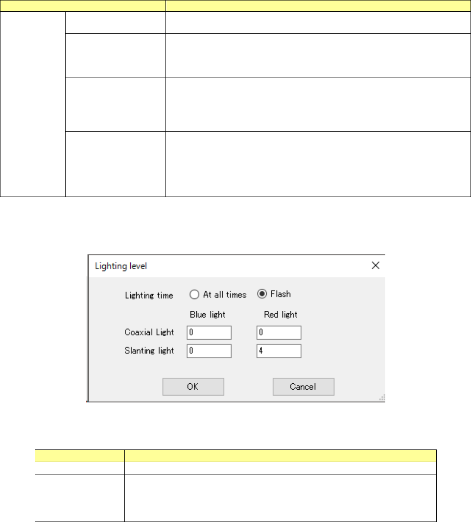
When you double-click the “Lighting level” cell, the screen like one shown below appears, and you
can set the light level.
Figure 7.4-9 RX-7 Series Lighting level screen
Table 7.4-6 Setting items to RX-7 Series Lighting level
Item
Contents
Lighting time
Choose from at all times or Flash.
Lighting value
Set brightness of each lighting at the time of the mark recognition.
In the case of at all times, you will input range from 0 to 4.
In the case of Flash, it will input range is 0 to 8.
Default value is 4.
JaNets Instruction Manual 7. Program Editor
7-14
Editing PWB Data (Circuit Layout)
When you select the “PWB Data” from the tree view, and then the “Circuit Layout A” or “Circuit
Layout B,” the following screen appears. When you do not select “Non-matrix circuit” as the “PWB
Configuration,” or when you select “Do not use” as the “Reference Circuit,” you cannot enter any
value on this screen.
When PWB configuration is the "single circuit," the "circuit layout A" cannot be selected.
In the following cases, the "circuit layout A" can be selected.
- When PWB configuration is the "non-matrix circuit,"
- When PWB configuration is the "matrix circuit" or the "non-matrix circuit" and the “Extension”
is selected for specifying bad mark coordinates through the "PWB data" - "Basic setting” and
the bad mark is set to the “Use” through the “PWB data” – “Circuit setting A.”
- When PWB configuration is the "matrix circuit" or the "non-matrix circuit" and the “Extension”
is selected for specifying bad mark coordinates through the "PWB data" - "Basic setting” and
the placement circuit specification is set to the “Use” through the “PWB data” – “Circuit setting
A.”
- When the production line includes an RV-1 and/or an RV-2, the “Matrix Circuit” or “Non-matrix
Circuit” is selected as the “PWB Configuration,” “Use” is selected for the “L/R Use Same Bad
Mark Recognition” on the “PWB Data” – “Basic Settings,” and “Use” is selected as the “Bad
Mark”
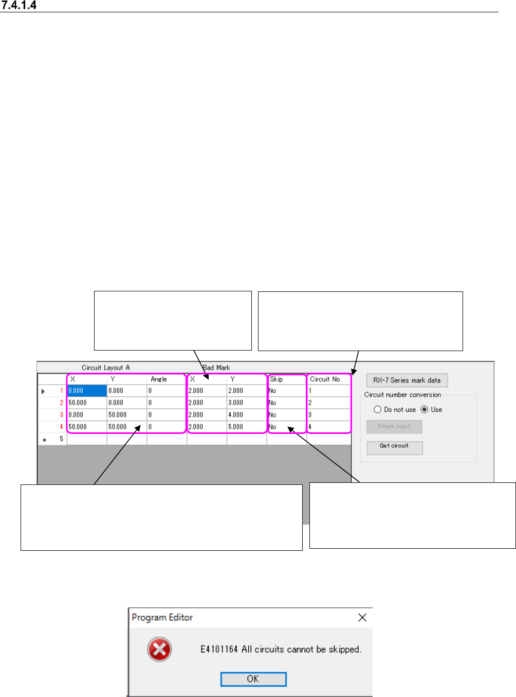
Figure 7.4-10 Example of the “PWB Data (Circuit Layout)” screen
A circuit skip can be set to the "Yes" in no circuits.
Figure 7.4-11 Skip Setting Error
It is an item that can be entered only when PWB configu-
ration is the "non-matrix circuit." If it is the "matrix circuit,"
the item cannot be changed. The circuit coordinates are
calculated with the circuit information set in the "PWB da-
ta"- “Circuit setting A” to display.
Enter extended bad mark co-
ordinates. It is an item which is
not displayed when not using
an extended bad mark.
Specify the circuit to place components.
Right-click to select the "Yes" or "No." A
default is "No" (circuit to place). It is an
item that is not displayed when the
placement circuit specification is not used
Enter the circuit number used with the
upload machine. This menu item is dis-
played only when “Use” is selected for the
menu item “Circuit number conversion.”
JaNets Instruction Manual 7. Program Editor
7-15
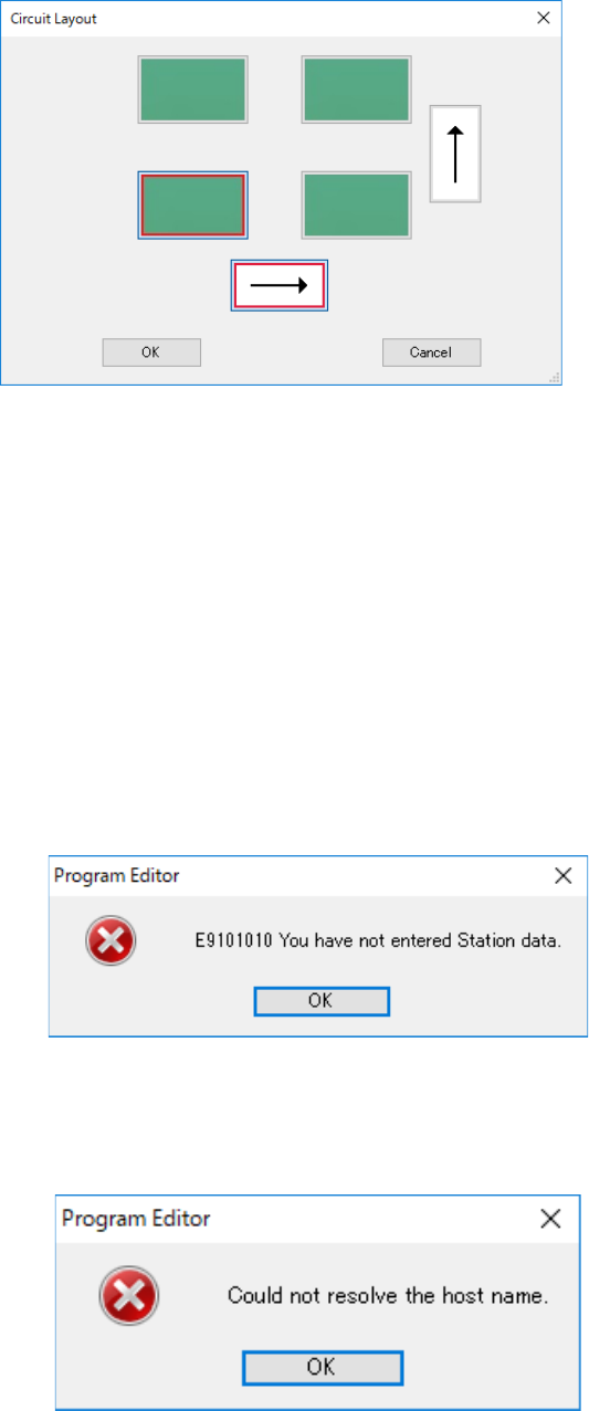
When you press the <Simple Input> button of the menu item “Circuit number conversion,” the fol-
lowing screen appears.
(This <Simple Input> button is displayed only when “Matrix Circuit” is selected as the “PWB Con-
figuration.” When “Non-matrix Circuit” is selected, it is not displayed on the screen.)
Figure 7.4-12 Simple input screen for entering a circuit number
When you specify the reference circuit position and the expanding direction, the system automat-
ically sets the circuit assignment order of the machine for uploading data.
Reference circuit position: Lower left, Lower right, Upper left and Upper right
Expanding direction: Horizontal direction and Vertical direction
Initial setting: The reference circuit position is at the lower left, and the expanding direction is
horizontal (Juki standard assignment order).
When you press the <Get circuit> button of the menu item “Circuit number conversion,” the system
obtains the circuit number information from a machine for which “Use” of the menu item “L/R Use
Same Bad Mark Recognition” is selected with Shopfloor Setup.
If any item such as the production program name of the station data is not entered yet, the fol-
lowing message appears on the screen.
Figure 7.4-13 Data uninput error
Open the tab of the machine for uploading data on the “Station data” screen, and then enter the
necessary information.
If the system fails to find a machine whose IP address is set with Shopfloor Setup, the following
message appears on the screen.
Figure 7.4-14 Error caused because the specified machine is not found