JANETS_INM.pdf - 第229页
JaNets In structio n Manual 7. Program Editor 7- 22 A rea Fiduci al Mark W hen you sel ect “ Ed it ” or “ Browse ” in a “ Ma rk ” cell on the “ Plac ement Dat a ” screen, the “ Area Fiducial M ark ” sett ing scre en appe…
JaNets Instruction Manual 7. Program Editor
7-21
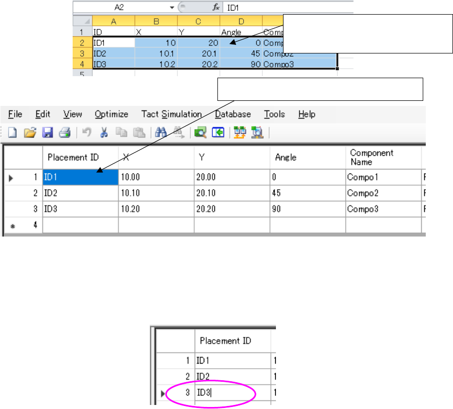
Placement ID and component name can be copied and pasted with the Ctrl+C key and the Ctrl+V
key.
Regarding the placement ID, placement coordinates X/Y, angle, and component name, the data
created with another text editor or Excel can be copied with the Ctrl + C key, and then pasted with
the Ctrl + V key.
Figure 7.4-26 Copy and paste operation on the Placement data list screen
(If a comma is included in the placement ID, it cannot be pasted correctly. Convert it to another
character and then perform pasting.)
However, when the cell of placement ID and component name is editing, placement ID and com-
ponent name cannot be copied and pasted with the Ctrl+C key and the Ctrl+V key.
Figure 7.4-27 You cannot perform the Ctrl + V operation while editing a “Placement ID.”
Moreover, when the cell of placement ID and component name has a cursor, the "copy" and “paste”
of an edit menu cannot be performed. (The copy and paste of an edit menu is performed to a line
of placement data.)
* In the EPU mode, “Placement/application”, “Machine specification”, “Application skip”,
“Application test” and “Application machine specification” are not displayed.
In the line mode, “Placement head specification” is not displayed.
* Placement layer
A placement layer (displayed in the “Layer” column) is set in “the priority order of placement,”
and you can enter a value in the range of 1 to 10,000 when you use an RX-7 series.
When the placement data is uploaded changing the input range from 8 to 10,000 on the side of
an RX-7 series after being downloaded with the JaNets, the Program Editor considers the
placement data incomplete. (The layer is supposed to be blank.)
In order to re-optimize the placement data, set up again in the range of the layer 1 to 7.
The data row entered with Excel can
be copied at a time.
Copied data is pasted to the “Placement ID”
JaNets Instruction Manual 7. Program Editor
7-22
Area Fiducial Mark
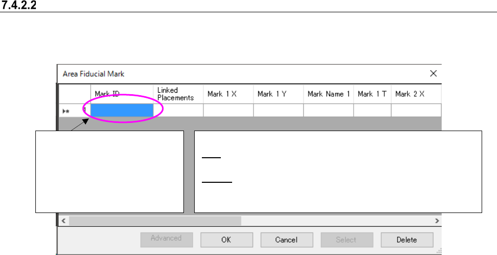
When you select “Edit” or “Browse” in a “Mark” cell on the “Placement Data” screen, the “Area
Fiducial Mark” setting screen appears.
Figure 7.4-28 “Area Fiducial Mark” screen
Mark ID can be copied and pasted with the Ctrl+C key and the Ctrl+V key.
However, when the cell of mark ID is editing, the mark ID cannot be copied and pasted with the
Ctrl+C key and the Ctrl+V key.
[When a JX-350 and RS-1 are used]
If you finish creating one piece of mark data when you select “LED” as the “Mark Type,” the system
determines that Placement data has been completed.
<Operations of the buttons when “Edit” is selected>
OK: Goes back to the “Placement Data” screen, and saves the
input data. “NO” is displayed in the “Mark” cell.
Select: Goes back to the “Placement Data” screen, and displays
the selected mark ID in the “Mark” cell.
<Operations of the buttons when “Browse” is selected>
The mark ID is displayed in the
format “Mxxxx”
(up to eight characters).
The format “Sxxxx” (up to eight
characters): when Mark Type
is ”Solder” or “Solder (PWB)”.
JaNets Instruction Manual 7. Program Editor
7-23
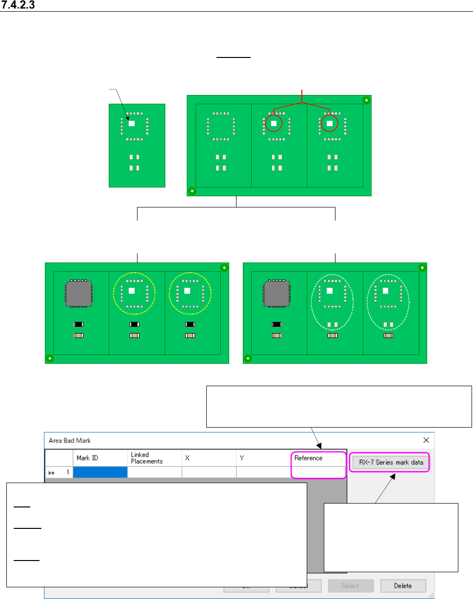
Area Bad Mark
When you select “Edit” or “Browse” in an “Area Bad Mark” cell on the “Placement Data” screen,
the “Area Bad Mark” setting screen appears. You can set up to 10,000 bad marks for each com-
ponent placement positions. See
Section “7.4.2.2 Area Fiducial Mark” for how to set data.
U1
U1
U1
U1
U1
U1
U1
R10
U1
U1
U1
C10
R10
C10
R10
C10
R10
C10
R10
C10
R10
C10
R10
C10
R10
C10
R10
C10
R10
C10
Circuit
Circuit
Circuit
Circuit
Circuit
Circuit
Circuit
Circuit
Circuit
Circuit
Figure 7.4-29 Image for setting an area bad mark
Figure 7.4-30 “Area Bad Mark” screen
Mark ID can be copied and pasted with the Ctrl+C key and the Ctrl+V key.
However, when the cell of mark ID is editing, the mark ID cannot be copied and pasted with the
Ctrl+C key and the Ctrl+V key.
Bad mark ID
BM001
Bad marks exist on a board.
When the bad mark ID “BM001” is assigned
to a component placement position “U1”
When the bad mark ID “BM001” is assigned to
component placement positions “U1” and “R10”
<Operations of buttons when you select “Edit”>
OK: Goes back to the “Placement Data” screen, and saves the input data. “NO”
appears in the “Mark” cell.
Select: Goes back to the “Placement Data” screen, and the selected mark ID is
displayed in the “Mark” cell.
<Operations of buttons when you select “Browse”>: The <OK> button is disabled.
Delete: Deletes bad mark data, changes all “Area Bad Mark” settings of Placement
data that use the selected bad mark ID to “NO” and goes back to the “Placement
Data” screen.
Reference: Sets the reference position of coordinates. When
you click the right button of a mouse, you can select one of the
followings: “Reference Circuit,” and “Circuit Origin.”
Sets bad mark information for
an RX-7 series.
See Section 7.4.1.3.1 “RX-7
series bad mark information”
for the detailed settings.