JANETS_INM.pdf - 第233页
JaNets In structio n Manual 7. Program Editor 7- 26 “ Basic Settings ” sc reen This scree n allows y ou to create t he basic dat a such as t he component type, component pack- aging sty le, outer dim ensions and center i…
JaNets Instruction Manual 7. Program Editor
7-25
7.4.3 Editing component data
Displaying the component data list
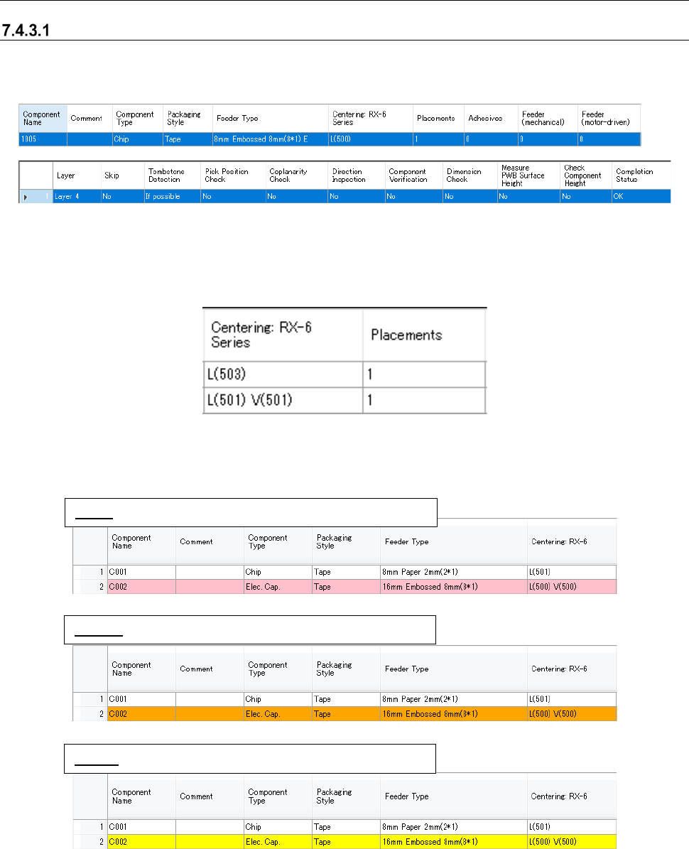
When you select the “Component Data” from the tree view, the following screen appears. Com-
ponent data not linked with any placement data is also displayed.
Figure 7.4-32 Component data list
The “Centering (nozzle number)” item to be displayed varies depending on the machine model as
shown below. Only the “Centering” item corresponding to the machine model that configures the
selected production line is displayed.
When the selected production line consist of an RX-6.
Figure 7.4-33 Displayed nozzle pattern
The state indicated with each color on the “Component Data” screen is described below.
Figure 7.4-34 Component data list – displayed colors
* When you perform a key operation: Ctrl + drag and Ctrl + drop or Ctrl +C key and Ctrl +V key for
a line of data on the Component data list screen, you can overwrite the component data with the
copied data.
Pink: Component data not linked with any placement data.
Orange: Data on a component to be skipped.
Yellow: Not completed component data.
JaNets Instruction Manual 7. Program Editor
7-26
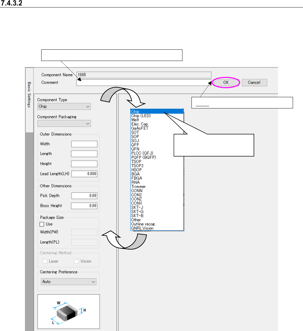
“Basic Settings” screen
This screen allows you to create the basic data such as the component type, component pack-
aging style, outer dimensions and centering method. When you double-click a line on the
“Placement Data list” or “Component data list” described above, this screen appears.
Figure 7.4-35 “Basic Settings” screen
[When a production line includes a JM series machine]
“Insertion component” and “INS electrolytic capacitor” are added to the component types.
[When a production line includes a JM series machine, a JX-350 and an RS-1]
Package Size is enabled. When the package size is used, the package size is used for the di-
mensions and outside dimensions of deciding default value.
OK: Validates the changed data.
You can enter up to 127 half-width characters here.
When you select “Chip,” its
bit map is displayed also.
JaNets Instruction Manual 7. Program Editor
7-27
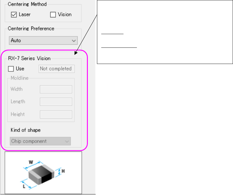
To create data for an RX-7 series, put a checkmark in the “Use” check box of the “RX-7 series Vi-
sion” column. You can set data related to an RX-7 series.
Figure 7.4-36 “Basic Settings” screen (RX-7 Series Vision)
To assign an RX-7 series you have to set data for an
RX-7 series. Therefore, put a checkmark in the “Use”
check box. The default setting for putting a checkmark
in this check box can be made on the “Set environ-
ments” screen.
Mold line: Set the dimensions of the molded section
as the size of the component body.
Kind of shape: Select the component shape type
defined with an RX-7 series