JANETS_INM.pdf - 第239页
JaNets In structio n Manual 7. Program Editor 7- 32 Laser Ce ntering The typica l laser cent ering screen of RX -6 ser ies is s hown below . Figure 7.4 - 45 Examp le of th e laser cent ering scr een ( RX -6 S eri es ) Th…
JaNets Instruction Manual 7. Program Editor
7-31
“Laser Centering General Settings” screen
When you check the “Laser” check box in the “Centering Method” column of the “Basic Settings”
screen, and select the “Component Data” from the tree view, and then the “Laser Centering,” the
following screen appears.
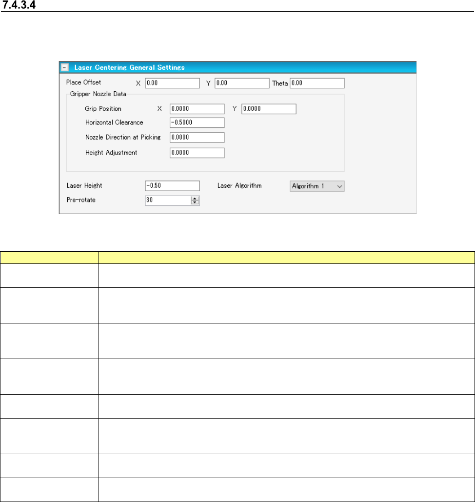
Figure 7.4-44 “Laser Centering General Settings” screen
Table 7.4-10 Laser centering shared settings screen item
Item
Description
Place Offset
Specify an offset value of an asymmetrical component to be applied when it is placed on a
board.
Gripper Nozzle Data
Grip Position
Enter an offset value to the center of a surface pressing the arm to fix the gripper nozzle from
the center of component into Y.
Do not enter any values other than zero into X.
Gripper Nozzle Data
Horizontal Clearance
Specify the clearance between a surface pressing the arm to fix the gripper nozzle and the
component using using a minus.
Note that a moving direction changes depending on a nozzle type and directions of a nozzle.
Gripper Nozzle Data
Nozzle Direction at
Picking
This is the direction of a nozzle at the time of pickup when components are supplied at 0 de-
gree.
Specify 0 degree, 90 degrees, 180 degrees, or 270 degrees.
Gripper Nozzle Data
Height Adjustment
Enter the offset value (sharing with the amount of stroke) of the pickup height at the time of
pickup.
Laser Height
Specify the measurement height at the time of laser centering.
When there is nothing in the setting item by machine type, this data is referred to as a laser
height.
Laser Algorithm
Specify the algorithm for laser recognition from a combo box.
An RX-6 does not need the setting of this item.
Pre-rotate
Specify how much a picked up laser recognition component is rotated before centering.
An RX-6 does not need the setting of this item.
JaNets Instruction Manual 7. Program Editor
7-32
Laser Centering
The typical laser centering screen of RX-6 series is shown below.
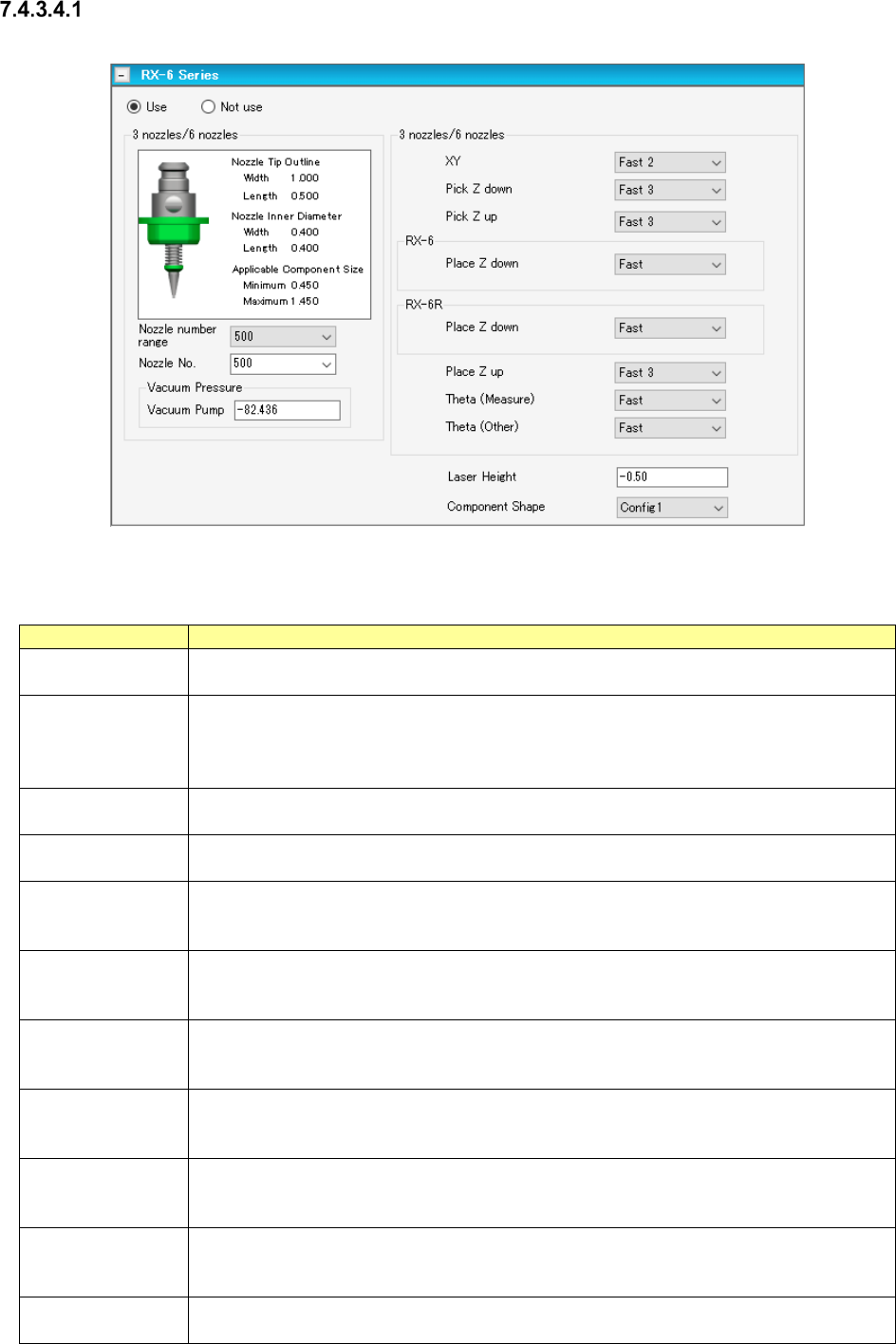
Figure 7.4-45 Example of the laser centering screen (RX-6 Series)
The description of each item on the laser centering screen is shown in the table below.
Table 7.4-11 Displayed items of the laser centering screen (RX-6 Series)
Item
Description
Use/Not use
Select whether to use the laser centering information or not.
The “Use” radio button is selected by default.
Nozzle No.
Select a nozzle number that is used to pick up a component from the drop-down list of the
combo box. The nozzle numbers set on the “Equipment Setup” screen of the Shopfloor
Setup application are displayed on the drop-down list.
The default value is decided according to the component type and the outer dimensions.
Vacuum Pressure
Ejector
Enter the vacuum pressure to be applied when a component is picked up.
The default value is decided according to the component type and the outer dimensions.
Vacuum Pressure
Vacuum Pump
Enter the vacuum pressure to be applied when a component is picked up.
The default value is decided according to the component type and the outer dimensions.
XY Select the acceleration of the XY-axes to be applied from when a component is picked up
until when the axes move to the component placement position from the combo box.
The default value is decided according to the component type and the outer dimensions.
Pick Z down/up
Select the acceleration of the Z-axis to be applied when it moves down or up to pick up a
component.
The default value is decided according to the component type and the outer dimensions.
Place Z down/up Select the acceleration of the Z-axis to be applied when it moves down or up to place a
component on a board.
The default value is decided according to the component type and the outer dimensions.
Theta (Measure)
Select the acceleration of the theta axis to be applied when a component is recognized with
laser from the combo box.
The default value is decided according to the component type and the outer dimensions.
Theta (Other) Select the acceleration of the theta axis to be applied unless a component is recognized
with laser from the combo box.
The default value is decided according to the component type and the outer dimensions.
Laser Height
Enter an offset from the top side of a component to the laser surface.
Input range: - 25.00 to 10.00 mm
The default value is decided according to the component type and the component height.
Component Shape Select the shape of a component to be used for laser recognition from the combo box.
Select the shape among “Config0,” “Config1,” “Config2,” “Config3” and “Config5.”
JaNets Instruction Manual 7. Program Editor
7-33
Laser Centering (JM-20 Series)
The typical laser centering screen of JM series machine is shown below.
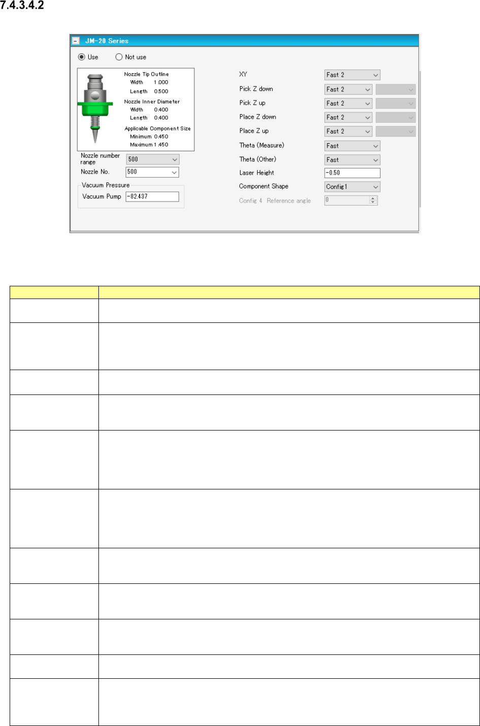
Figure 7.4-46 Laser centering screen example (of JM-20 Series)
The typical laser centering screen of a JM series machine is shown below.
Table 7.4-12 Laser centering screen example (of JM-20 Series)
Item
Description
Use/Not use
Select whether to use the laser centering information or not.
The “Use” radio button is selected by default.
Nozzle No.
Select a nozzle number that is used to pick up a component from the drop-down list of the
combo box. The nozzle numbers set on the “Equipment Setup” screen of the Shopfloor
Setup application are displayed on the drop-down list.
The default value is decided according to the component type and the outer dimensions.
Vacuum Pressure
Vacuum Pump
Enter the vacuum pressure to be applied when a component is picked up.
The default value is decided according to the component type and the outer dimensions.
XY
Select the acceleration of the XY-axes to be applied from when a component is picked up
until when the axes move to the component placement position from the combo box.
The default value is decided according to the component type and the outer dimensions.
Pick Z down/up
Select the acceleration of the Z-axis to be applied when it moves down or up to pick up a
component.
The default value is decided according to the component type and the outer dimensions.
When you select “Fast,” “Medium” or “Slow” here, you can also select the more detailed
speed from “Speed 1” (slowest) to “Speed 5” (Fastest).
Place Z down/up
Select the acceleration of the Z-axis to be applied when it moves down or up to place a
component on a board.
The default value is decided according to the component type and the outer dimensions.
When you select “Fast,” “Medium” or “Slow” here, you can also select the more detailed
speed from “Speed 1” (slowest) to “Speed 5” (Fastest).
Theta (Measure)
Select the acceleration of the theta axis to be applied when a component is recognized with
laser from the combo box.
The default value is decided according to the component type and the outer dimensions.
Theta (Other)
Select the acceleration of the theta axis to be applied unless a component is recognized with
laser from the combo box.
The default value is decided according to the component type and the outer dimensions.
Laser Height
Enter an offset from the top side of a component to the laser surface.
Input range: - 25.00 to 10.00 mm
The default value is decided according to the component type and the component height.
Component Shape
Select the shape of a component to be used for laser recognition from the combo box.
Select the shape among “Config0,” “Config1,” “Config2,” “Config3” and “Config5.”
Config 4 Refer-
ence angle
You can set this item only when you select “Configu4” as the “Component Shape.”
The initial value of this “Config 4 Reference angle” is 0. The input range is from 0 to 359.
Even though you change the setting of the “Component Shape” from “Config 4” to another
choice, this “Config 4 Reference angle” setting will not be initialized.