JANETS_INM.pdf - 第244页
JaNets In structio n Manual 7. Program Editor 7- 37 Vision centering ( JM - 20 S eries ) The typica l vis ion centering screen o f JM - 2 0 series machine is show n bel ow . Figure 7.4 - 51 Example of the vision ce nteri…
JaNets Instruction Manual 7. Program Editor
7-36
Table 7.4-14 Items displayed on the vision centering screen (RX-7 Series)
Item
Description
Use/Not use
Select whether to use the RX-7 series vision centering information or not.
*If you select the “Not use” radio button, any centering data is not set when you use the
Program Editor to invoke Component data. Therefore, enable the vision centering function
with the Component Database first before invoking the Component data.
Motion data
Nozzle No.
Select a prior nozzle from the drop-down list located on the combo box.
Motion data
Override: XY.
Enter the XY override ratio
Input range:1 to 100
Motion data
Override: Feeder
Enter the feeder override ratio.
When the tape width is 8 mm, select the speed among “Fast 2,” “Fast,” “Middle,” Slow.”
When you use any other width tape, select the speed among “Fast 2,” “Middle” and “Slow.”
Motion data
Override: H(Pick)
Enter the override ratio of the Height (for picking up a component).
Input range:1 to 100
Motion data
Override:
H(Pre-place)
Enter the override ratio of the Height (applied before placing a component on a board).
Input range:1 to 100
Motion data
Override:
H(Post-place)
Enter the override ratio of the Height (applied after placing a component on a board).
Input range:1 to 100
Motion data
Override: RTRN
Enter the RTRN override ratio.
Input range:1 to 100
Recognition Off-
set X Y
Enter offset viewed from the center of a component when the component is recognized with a
VCS.
Input range: -999.99 to 999.99.
Precision level
Apply this level to a component whose height and position have to be set precisely when it is
placed on a board.
Select either “Ordinary operation” or “High-precision operation.”
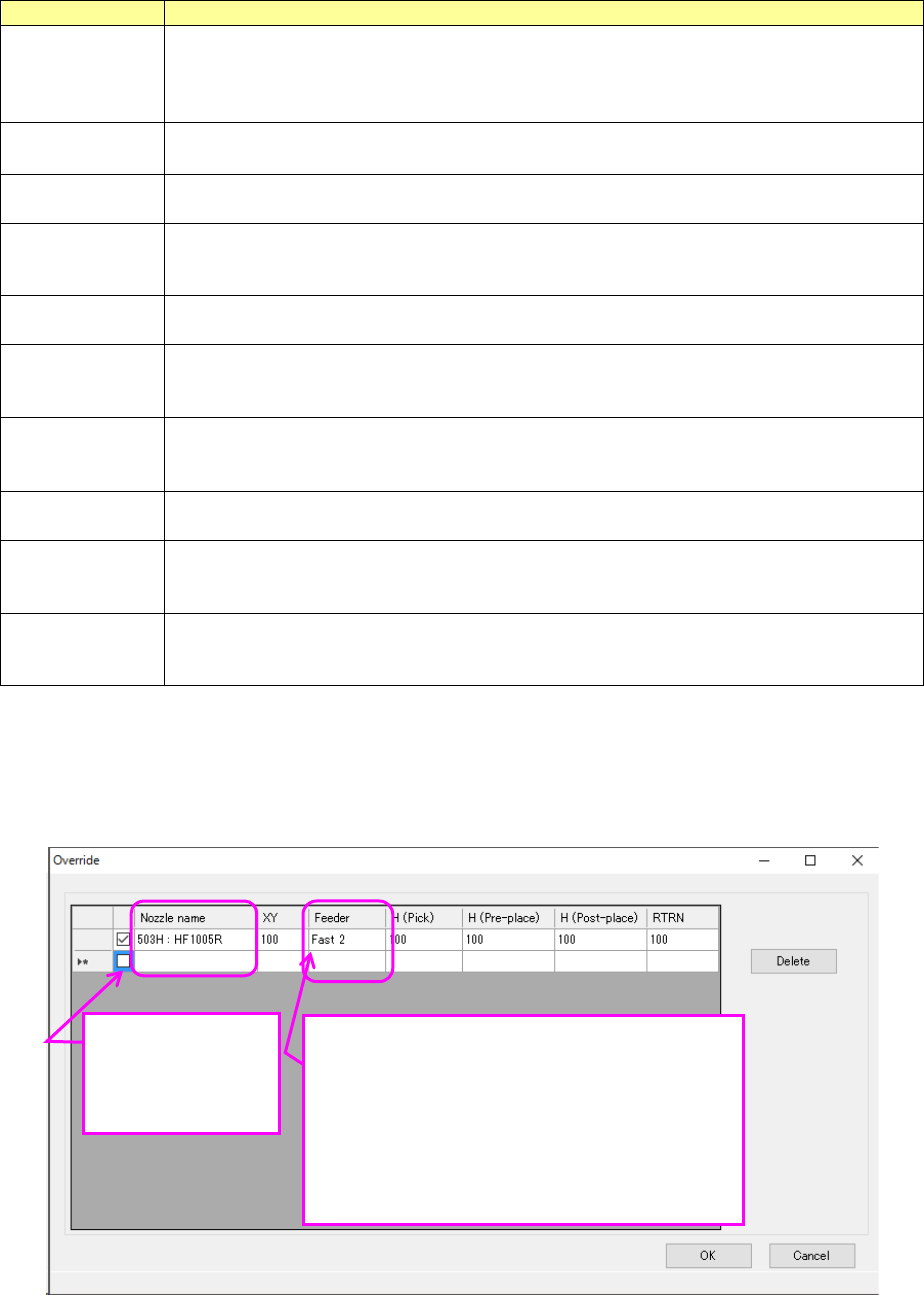
When you press the <Override> button, the following screen appears.
Edit, add or delete a nozzle number and an override that can be used with the corresponding
component.
A nozzle whose check box a checkmark is put in is handled as a prior nozzle.
Figure 7.4-50 RX-7 Series “Override” setting screen
Specify the noz-
zle number.
Select one of the
imported nozzles
Enter the feeder override ratio.
When the tape width is 8 mm, select the
speed among “Fast 2,” “Fast,” “Middle,”
Slow.”
When you use any other width tape, select
the speed among “Fast 2,” “Middle” and
“Slow.”
JaNets Instruction Manual 7. Program Editor
7-37
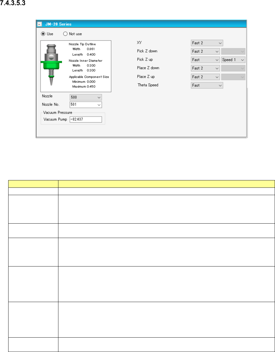
Vision centering (JM-20 Series)
The typical vision centering screen of JM-20 series machine is shown below.
Figure 7.4-51 Example of the vision centering screen (JM-20 Series)
The items displayed on the vision centering screen are shown in the table below.
Table 7.4-15 Items displayed on the vision centering screen (JM-20 Series)
Item
Description
Use/Not use
Select whether to use the vision centering information or not.
Nozzle No.
Select a nozzle number that is used to pick up a component from the drop-down list of the
combo box. The nozzle numbers set on the “Equipment Setup” screen of the Shopfloor
Setup application are displayed on the drop-down list.
The default value is decided according to the component type and the outer dimensions.
Vacuum Pressure
Vacuum Pump
Enter the vacuum pressure to be applied when a component is picked up.
The default value is decided according to the component type and the outer dimensions.
XY
Select the acceleration of the XY-axes to be applied from when image of a component is
obtained until when the axes move to the corrected placement position from the combo
box.
The default value is decided according to the component type and the outer dimensions.
Pick Z down/up
Select the acceleration of the Z-axis to be applied when it moves down or up to pick up a
component.
The default value is decided according to the component type and the outer dimensions.
When you select “Fast,” “Medium” or “Slow” here, you can also select the more detailed
speed from “Speed 1” (slowest) to “Speed 5” (Fastest).
Place Z down/up
Select the acceleration of the Z-axis to be applied when it moves down or up to place a
component on a board.
The default value is decided according to the component type and the outer dimensions.
When you select “Fast,” “Medium” or “Slow” here, you can also select the more detailed
speed from “Speed 1” (slowest) to “Speed 5” (Fastest).
Theta Speed
Select the theta axis rotation speed from the combo box.
The default value is decided according to the component type and the outer dimensions.
JaNets Instruction Manual 7. Program Editor
7-38
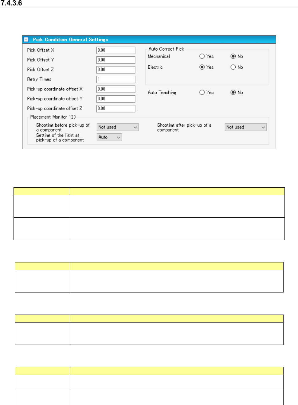
“Pick Conditions General Settings” screen
When you select “Component Data” from the tree view, and then “Pick Conditions,” the following
screen appears.
Figure 7.4-52 Pick conditions general setting screen
Pick offset: The pick conditions are set when components are not picked normally because there
is any protrusion or dent in the center of components.
Item
Description
Pick offset X and Y Specifies the distance from a center of component to pick coordinate at the time of
component pick. It is adjusted by the initial value of XY coordinates automatically
computed at the time of pick data creation.
Pick offset Z
Specifies the stroke distance from pick standard height to the nozzle chip at the time
of component pick. It is adjusted by the initial value of the Z coordinate automatically
computed at the time of pick data creation.
Pick position offset
Item
Description
Mechanical and
electric
Corrects a pick position gap based on a recognition result for the tape component of
laser centering. Specifies with a mechanical feeder and an electric feeder respec-
tively.
Pick-up coordinate offset
Item
Description
Pick-up coordinate
offset X, Y, Z
Adds or reduces to the initial value of the XY coordinates and Y coordinate that are
automatically calculated at creation of pick data. This function is effective only for
RX-6 series /RS-1 series.
Placement monitor 120
Item
Description
Pre-pick imaging
Post-pick imaging
Sets whether to perform imaging before/after pick by EPV.
This function is effective only for RX-6 series.
Pick lighting setting
Sets the brightness of lighting for imaging before/after pick by EPV.
This function is effective only for RX-6 series.
[When a production line includes a JM series machine]
None of the menu items “Pick Offset,” the “Electric” radio buttons of the menu item “Auto Correct Pick”
and the menu item “Placement Monitor 120” are displayed on the screen.