JANETS_INM.pdf - 第246页
JaNets In structio n Manual 7. Program Editor 7- 39 Pick conditions screen (FX -3 S er ies ) Figure 7.4 - 53 Pick conditions (FX -3 S eries ) scre en T able 7.4 - 16 Pick - up conditions ( FX -3 S eries ) screen i tem s …
JaNets Instruction Manual 7. Program Editor
7-38
“Pick Conditions General Settings” screen
When you select “Component Data” from the tree view, and then “Pick Conditions,” the following
screen appears.
Figure 7.4-52 Pick conditions general setting screen
Pick offset: The pick conditions are set when components are not picked normally because there
is any protrusion or dent in the center of components.
Item
Description
Pick offset X and Y Specifies the distance from a center of component to pick coordinate at the time of
component pick. It is adjusted by the initial value of XY coordinates automatically
computed at the time of pick data creation.
Pick offset Z
Specifies the stroke distance from pick standard height to the nozzle chip at the time
of component pick. It is adjusted by the initial value of the Z coordinate automatically
computed at the time of pick data creation.
Pick position offset
Item
Description
Mechanical and
electric
Corrects a pick position gap based on a recognition result for the tape component of
laser centering. Specifies with a mechanical feeder and an electric feeder respec-
tively.
Pick-up coordinate offset
Item
Description
Pick-up coordinate
offset X, Y, Z
Adds or reduces to the initial value of the XY coordinates and Y coordinate that are
automatically calculated at creation of pick data. This function is effective only for
RX-6 series /RS-1 series.
Placement monitor 120
Item
Description
Pre-pick imaging
Post-pick imaging
Sets whether to perform imaging before/after pick by EPV.
This function is effective only for RX-6 series.
Pick lighting setting
Sets the brightness of lighting for imaging before/after pick by EPV.
This function is effective only for RX-6 series.
[When a production line includes a JM series machine]
None of the menu items “Pick Offset,” the “Electric” radio buttons of the menu item “Auto Correct Pick”
and the menu item “Placement Monitor 120” are displayed on the screen.
JaNets Instruction Manual 7. Program Editor
7-39
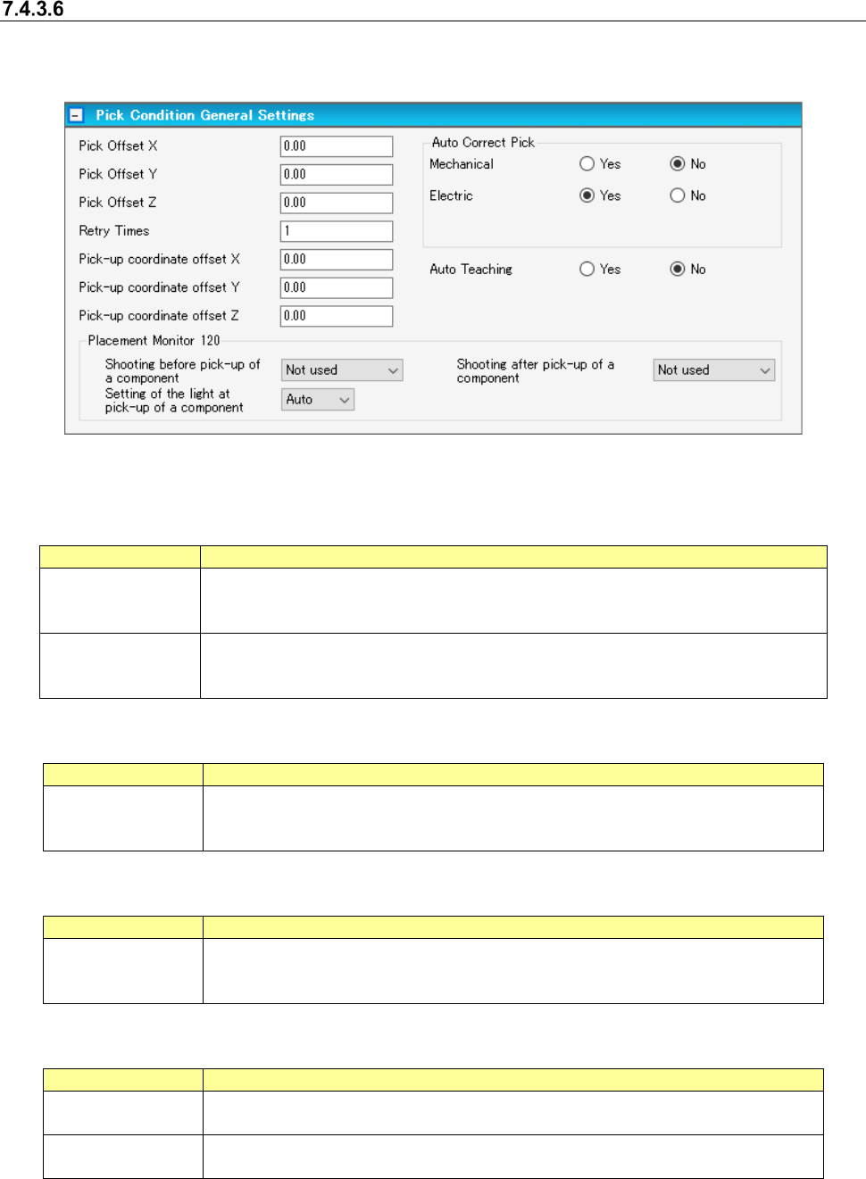
Pick conditions screen (FX-3 Series)
Figure 7.4-53 Pick conditions (FX-3 Series) screen
Table 7.4-16 Pick-up conditions (FX-3 Series) screen items
Item
Description
Z Two-Step Speed
Control
Specifies whether to control the up/down speed of the nozzle at pick by two steps.
For 2-step control, enter the height for 2-step control for each of up and down operations.
Picking Stroke Specifies the stroke of the nozzle end at component pick. To make an adjustment, enter
the adjusting time in the unit of mm.
Vacuum Control
Specifies whether to make an adjustment for vacuum time at pick. To make an adjustment,
enter the adjusting time in the unit of ms.
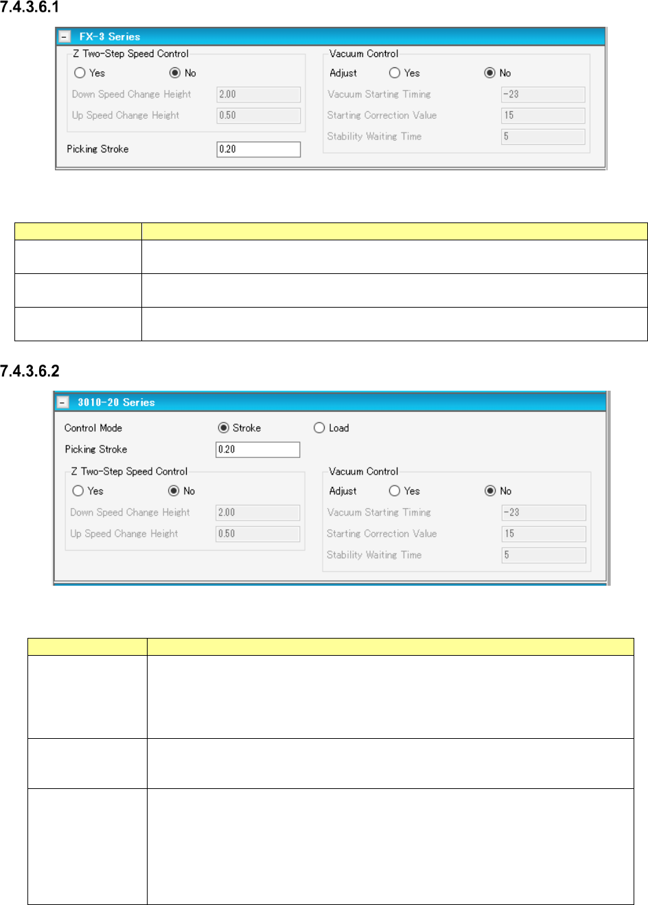
Pick conditions screen (3010-20 Series)
Figure 7.4-54 Pick conditions (3010-20 Series) screen
Table 7.4-17 Pick-up conditions (3010-20 Series) screen items
Item
Description
Stroke Specifies the distance of the stroke of the nozzle end at component pick. Enter it in
the unit of mm.
Default: 0.20 mm When the gripper nozzle is used: 0.000 mm When the packaging
style is “tray”: 1.000 mm When the side of the external dimensions is less than 0.45
mm: 0.000 mm
Load
Specifies the load for the stroke of the nozzle end at component pick. Enter it in the unit
of g. The input range and default value vary depending on the nozzle number and
centering condition.
Vacuum Control Specifies whether to adjust the vacuum time when a component is picked up.
To adjust the vacuum time, enter the adjusting time in ms.
*When you use a KE-3020 or a KE-3020R, the default value for a square chip whose
size is that of a 1005 chip or larger is different from the default value for other compo-
nents.
Set the correct default value by selecting the “Yes ” radio button for the menu item
“Adjust” with the machine again for data created with JaNets.
JaNets Instruction Manual 7. Program Editor
7-40
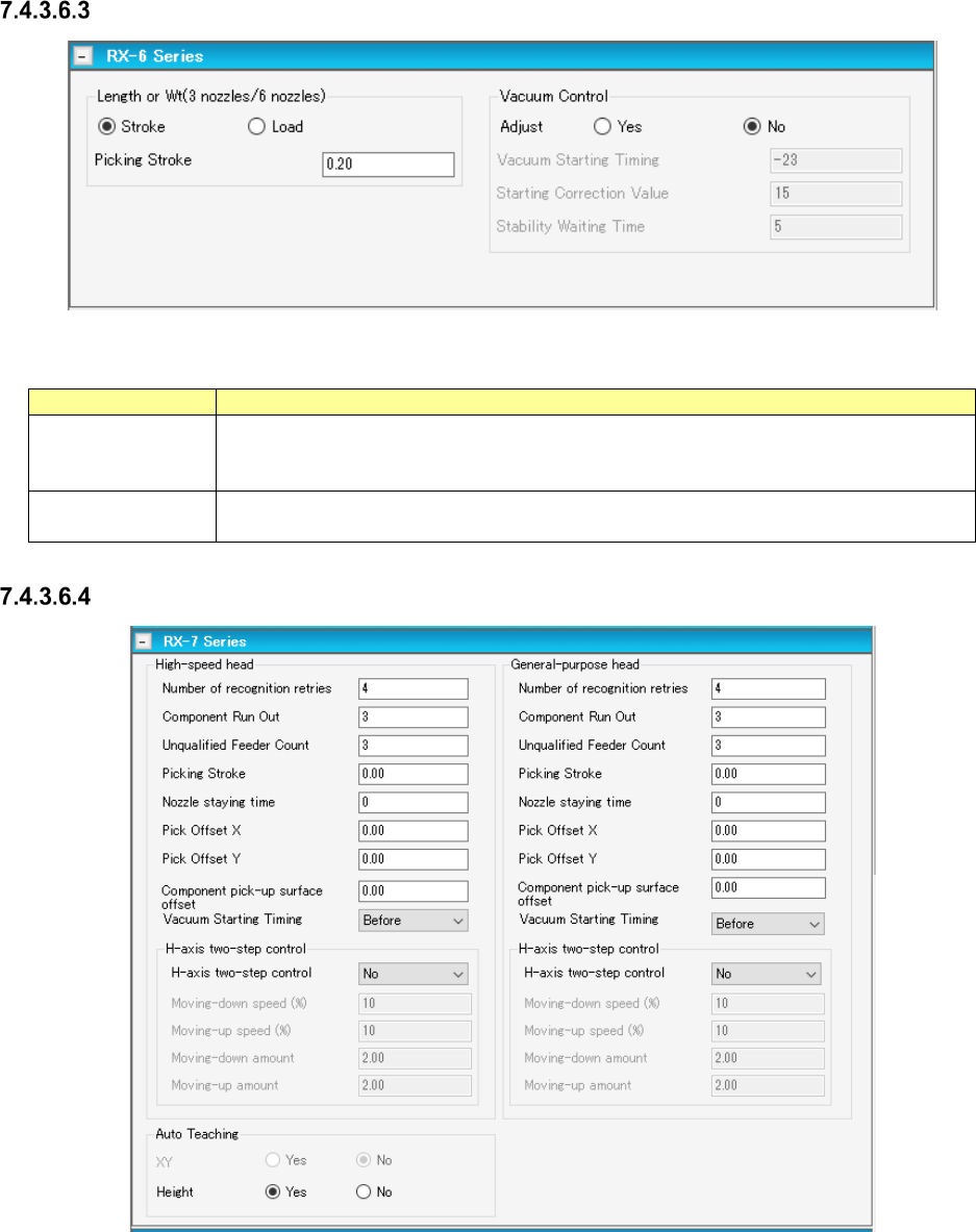
Pick conditions screen (RX-6 Series)
Figure 7.4-55 Pick conditions screen (RX-6 Series)
Table 7.4-18 Pick-up conditions (RX-6 Series) screen items
Item
Description
Picking stroke
Specifies how deep which a nozzle tip is pushed in at the time of component pick. Enter it
by mm (A default: 0.20 mm, for gripper nozzle use time: 0.00 mm, packaging is [tray]:
1.00 mm, when short sides of outer dimensions are less than 0.45 mm: 0.00 mm)
Vacuum Control
Specifies whether to adjust the vacuum time when a component is picked up.
To adjust the vacuum time, enter the adjusting time in ms.
Pick conditions screen (RX-7 Series)
Figure 7.4-56 Pick conditions screen (RX-7 Series)