JANETS_INM.pdf - 第254页
JaNets In structio n Manual 7. Program Editor 7- 47 Placement conditions screen ( FX -3 S eries ) Figure 7.4 - 65 Placement conditions (FX -3 S eries ) screen T able 7.4 - 29 Placeme nt condition (FX -3 S eries ) sc reen…
JaNets Instruction Manual 7. Program Editor
7-46
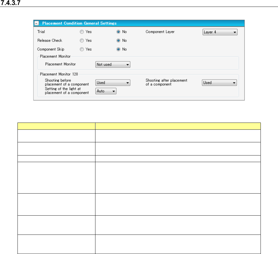
Placement conditions general setting screen
For component placement, settings are made according to the general data of the machine type.
Figure 7.4-64 Placement conditions general setting screen
Table 7.4-28 Placement condition common setting screen items
Item
Description
Trial
Specifies for every component whether the component is placed at
the time of execution of a trial.
Release Check
Specifies whether the component that is left after placement of laser
centering component is checked by laser.
Component Layer
Select placement sequence by component.
Placement Monitor
Specifies the operation of a placement monitor for every component.
Select one from among the “Not image” (default), “Image,” “Compo-
nent existence,” and “Movie.”
When you use a Placement Monitor for an RX-6, specify the "Place-
ment Monitor 120."
Placement Monitor 120
Shooting before placement
of a component
Specify whether or not to image before placement.
Placement Monitor 120
Shooting after placement of
a component
Specify whether or not to image after placement.
Placement Monitor 120
Setting of the light at
placement of a component
Select the light from "Auto" or 1~8 at the time of placement.
[When a production line includes a JM series machine]
None of the menu items, “Placement Monitor” “and “Placement Monitor 120” are displayed on the
screen.
JaNets Instruction Manual 7. Program Editor
7-47
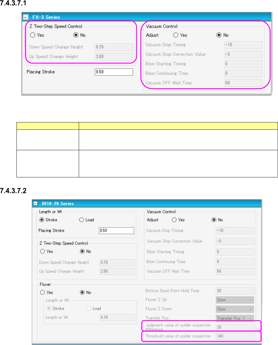
Placement conditions screen (FX-3 Series)
Figure 7.4-65 Placement conditions (FX-3 Series) screen
Table 7.4-29 Placement condition (FX-3 Series) screen items
Item
Description
Z Two-Step Speed
Control
Specifies whether to control the up/down speed of the nozzle at pick by two steps.
For 2-step control, enter the height for 2-step control for each of up and down
operations.
Vacuum Control
Specifies the stroke of the nozzle end at component pick. To make an adjust-
ment, enter the adjusting time in the unit of ms.
Specifies whether to make an adjustment for vacuum time at pick. To make an
adjustment, enter the adjusting time in the unit of ms.
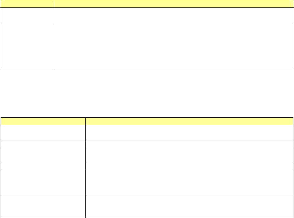
Placement conditions screen (3010-20 Series)
Figure 7.4-66 Placement conditions (3010-20 Series) screen
JaNets Instruction Manual 7. Program Editor
7-48
Table 7.4-30 Placement condition (3010-20 Series) screen items
Item
Description
Stroke
Selects either “stroke” or “load” as a specifying method for the stroke of the nozzle end at
component pick.
Vacuum Control
Specifies whether to adjust the vacuum time when a component is picked up.
To adjust the vacuum time, enter the adjusting time in ms.
*When you use a KE-3020 or a KE-3020R, the default value for a square chip whose size is
that of a 1005 chip or larger is different from the default value for other components.
Set the correct default value by selecting the “Yes ” radio button for the menu item “Adjust” with
the machine again for data created with JaNets.
- Fluxer: Specifies whether to perform flux applying process using a fluxer. To use the fluxer, the
centering condition is set to “Priority of vision centering.”
Table 7.4-31 Placement condition (3010-20 Series Fluxer) screen items
Item
Description
Stroke Sets how much stroke of the component for the top surface of the fluxer.
Select either “Stroke” or “Load” as the control method.
Bottom Dead Point Hold Time
Sets the wait time after the descent of the Z-axis of the head at fluxer transfer.
Fluxer Z Up/Down Sets the up/down speed of the Z-axis of the head when fluxer is transferred.
When “Load” is selected, the menu item “Fluxer Z down” is set to “FC speed.”
Transfer Pos.
Selects the fluxer transfer position.
Judgment value of solder in-
spection difference
Used for inspection to be performed at vision recognition before/after transfer.
This is a threshold value of brightness difference between two recognition visions.
This is an effective data when the rotary fluxer is used.
Threshold value of solder in-
spection
Used for inspection at vision recognition only after transfer.
Specifies the brightness power value.
This is an effective data when the rotary fluxer is used.
The fluxer can be set only when vision centering is used.
Therefore, if the nozzle to be set by vision is not a load nozzle, “Load” cannot be selected as the
control method.