JANETS_INM.pdf - 第265页
JaNets In structio n Manual 7. Program Editor 7- 58 Dimension Check Figure 7.4 - 82 “ Dimen sion Ch eck ” screen T able 7.4 - 47 C heck it ems displa yed on th e “ Dimension Che ck ” screen Item Description Check Yes /No…
JaNets Instruction Manual 7. Program Editor
7-57
Direction inspection
Figure 7.4-79 “Direction inspection” screen
Table 7.4-44 Inspection items displayed on the “Direction inspection” screen
Item Description
Check
Yes/No/
Select whether to conduct the direction inspection or not with the corresponding radio button.
You can select this menu item only when “SOT” or “GNRL Vision” is selected as the component
type. The “No” radio button is selected by default.
Component Verification
Figure 7.4-80 “Component Verification” screen
Table 7.4-45 Check items displayed on the “Component Verification” screen
Item Description
Check
Yes/No/
Select whether to check a resistance value, capacitance and polarity or not with
the corresponding radio buttons.
The “No” radio button is selected by default for all items.
Component Verifica-
tion
Resistance
You can enter these fields when you select the “Yes” radio button of the menu item
“Check.” Enter the judgment value, the unit, and the upper limit and lower limit of
the tolerance.
Select the unit from the combo box among: “Ω,” “KΩ” and “MΩ.”
The input range of the judgment value is 0.00 to 999.99. (Default: 0)
The input range of the upper limit is 0 to 100 %. (Default: 10)
The input range of the lower limit is – 100 to 0 %. (Default: 10)
Coplanarity Check
Electrode Width,
Length
You can enter these fields when you select the “Yes” radio button of the menu item
“Check.” Enter the judgment value, the unit, and the upper limit and lower limit of
the tolerance.
Select the unit from the combo box among: “pF” and “μF.”
The input range of the judgment value is 0.00 to 999999.99. (Default: 0)
The input range of the upper limit is 0 to 100 %. (Default: 80)
The input range of the lower limit is – 100 to 0 %. (Default: 20)
Component Verifica-
tion
Polarity
You can enter this field when you select the “Yes” radio button of the menu item
“Check.” Select the direction from the combo box.
Select “Right” (default), “Top,” “Left” or “Bottom.”
Polarity check
Figure 7.4-81 “Polarity check” screen
Table 7.4-46 Check item displayed on the “Polarity check” screen
Item
Description
Check
Yes/No/
Select whether to run a polarity check or not with the corresponding radio button.
You can set this item only when “INS electrolytic capacitor” is selected as the
component type.
JaNets Instruction Manual 7. Program Editor
7-58
Dimension Check
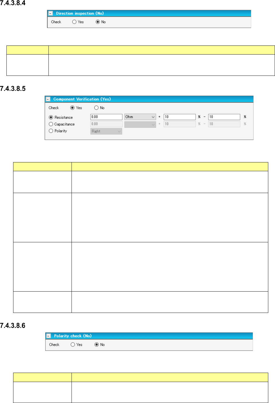
Figure 7.4-82 “Dimension Check” screen
Table 7.4-47 Check items displayed on the “Dimension Check” screen
Item
Description
Check
Yes/No
Select whether to run a dimension check or not with the corresponding radio button.
The “No” radio button is selected by default.
Dimension check
Standard Size
You can enter these fields when you select the “Yes” or “If possible” radio button of the
menu item “Check.” Enter the reference size of a component. The outer dimen-
sions are entered here by default.
Dimension check
Width Judge/Length
Judge
You can enter these fields when you select the “Yes” or “If possible” radio button of the
menu item “Check.” Enter the ratio to the component size.
Input range: 1 to 100 % (Default value: 15 %).
PWB Surface Height
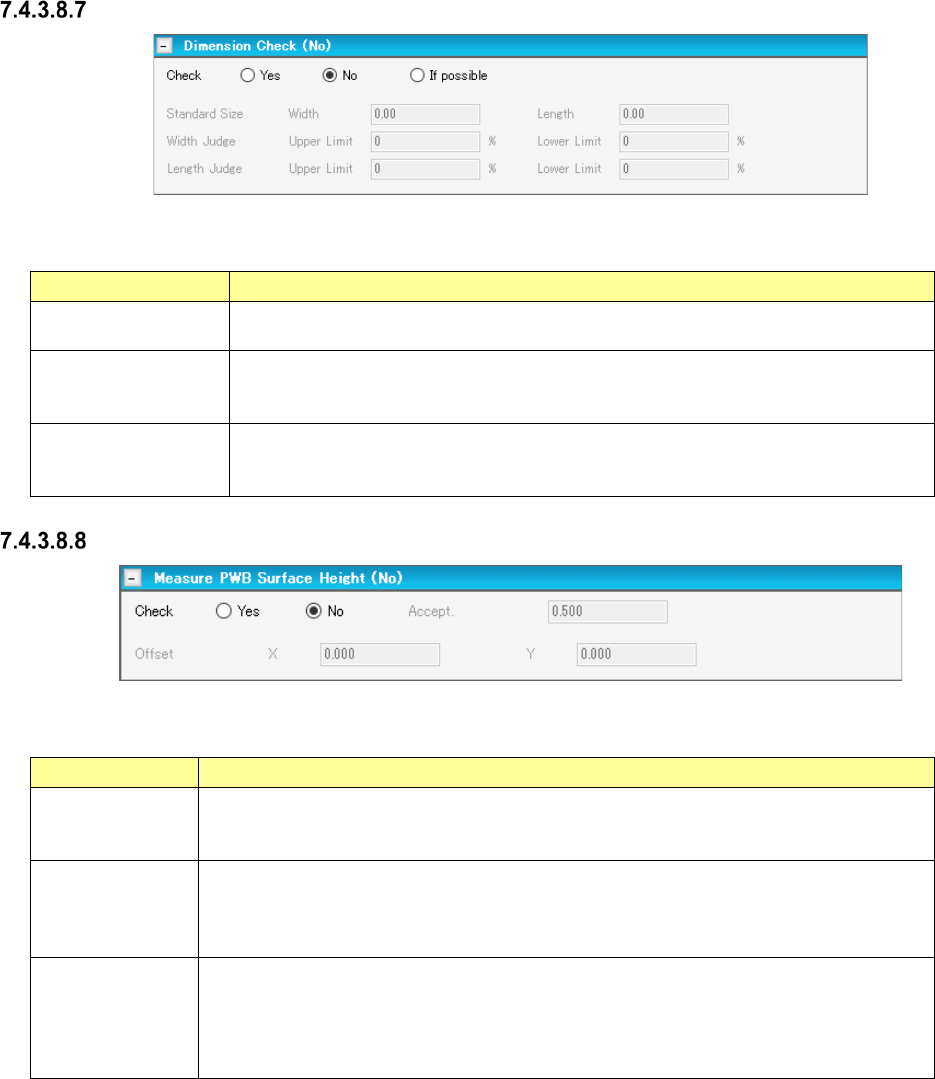
Figure 7.4-83 “Measure PWB Surface Height” screen
Table 7.4-48 Menu items displayed on the “Measure PWB Surface Height” screen
Item
Description
Check
Yes/No
Select whether to measure the height of the board surface on which a component is
placed with the corresponding radio button.
The “No” radio button is selected by default.
Measure PWB
Surface Height
Accept.
You can enter this field when you select the “Yes” radio button of the menu item “Check.”
Enter a judgment value for warpage of a board.
Input range: 0.00 to 5.00 mm
Default value: 0.50 mm
Measure PWB
Surface Height
Offset X, Y
You can enter these fields when you select the “Yes” radio button of the menu item
“Check.” Enter the offset from a component placement position to the component height
measurement position.
Input range: - 50.00 to 50.00 mm
Default value: 0.00 mm
JaNets Instruction Manual 7. Program Editor
7-59
Check Component Height
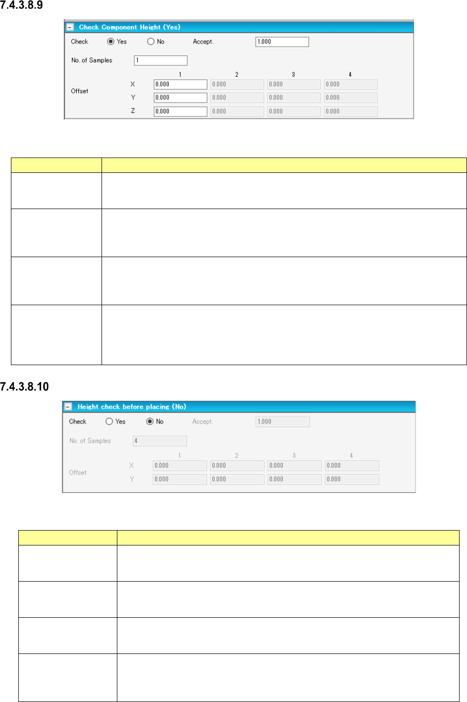
Figure 7.4-84 “Check Component Height” screen
Table 7.4-49 Check items displayed on the “Check Component Height” screen
Item Description
Check
Yes/No
Select whether to run a placed component height check or not with the corresponding
radio button.
The “No” radio button is selected by default.
Check Component
Height
Accept.
You can enter this field when you select the “Yes” radio button of the menu item “Check.”
Enter the judgment value based on the measurement result by the HMS.
Input range: 0.00 to 5.00 mm
Default value: 0.50 mm
Check Component
Height
No. of Samples
You can enter this field when you select the “Yes” radio button of the menu item “Check.”
Enter the number of check positions of a component.
Input range: 1 – 4
Default value: 4
Check Component
Height
Offset X, Y, Z
You can enter these fields when you select the “Yes” radio button of the menu item
“Check.” Enter the offset (X, Y) from the center of the component.
You can enter the offset values also for the number of components specified with the
menu item “No. of Samples.”
Offset Z entering becomes capable only for the line containing JM-100.
Height check before placing
Figure 7.4-85 “Height check before placing” screen
Table 7.4-50 Check items displayed on the “Height check before placing” screen
Item
Description
Check
Yes/No
Select whether to run a placed component height check or not with the correspond-
ing radio button.
The “No” radio button is selected by default.
Height check before
placing
Accept.
You can enter this field when you select the “Yes” radio button of the menu item
“Check.” Enter the judgment value based on the measurement result by the HMS.
Input range: 0.00 to 5.00 mm Default value: 0.50 mm
Height check before
placing
No. of Samples
You can enter this field when you select the “Yes” radio button of the menu item
“Check.” Enter the number of check positions of a component.
Input range: 1 – 4 Default value: 4
Height check before
placing
Offset X, Y
You can enter these fields when you select the “Yes” radio button of the menu item
“Check.” Enter the offset (X, Y) from the center of the component.
You can enter the offset values also for the number of components specified with the
menu item “No. of Samples.”