JANETS_INM.pdf - 第268页
JaNets In structio n Manual 7. Program Editor 7- 61 Determination of insertion of a componen t Figure 7.4 - 88 “ Determination of inse rtion of a component ” screen T able 7.4 - 53 Items displayed on the “ Determination …
JaNets Instruction Manual 7. Program Editor
7-60
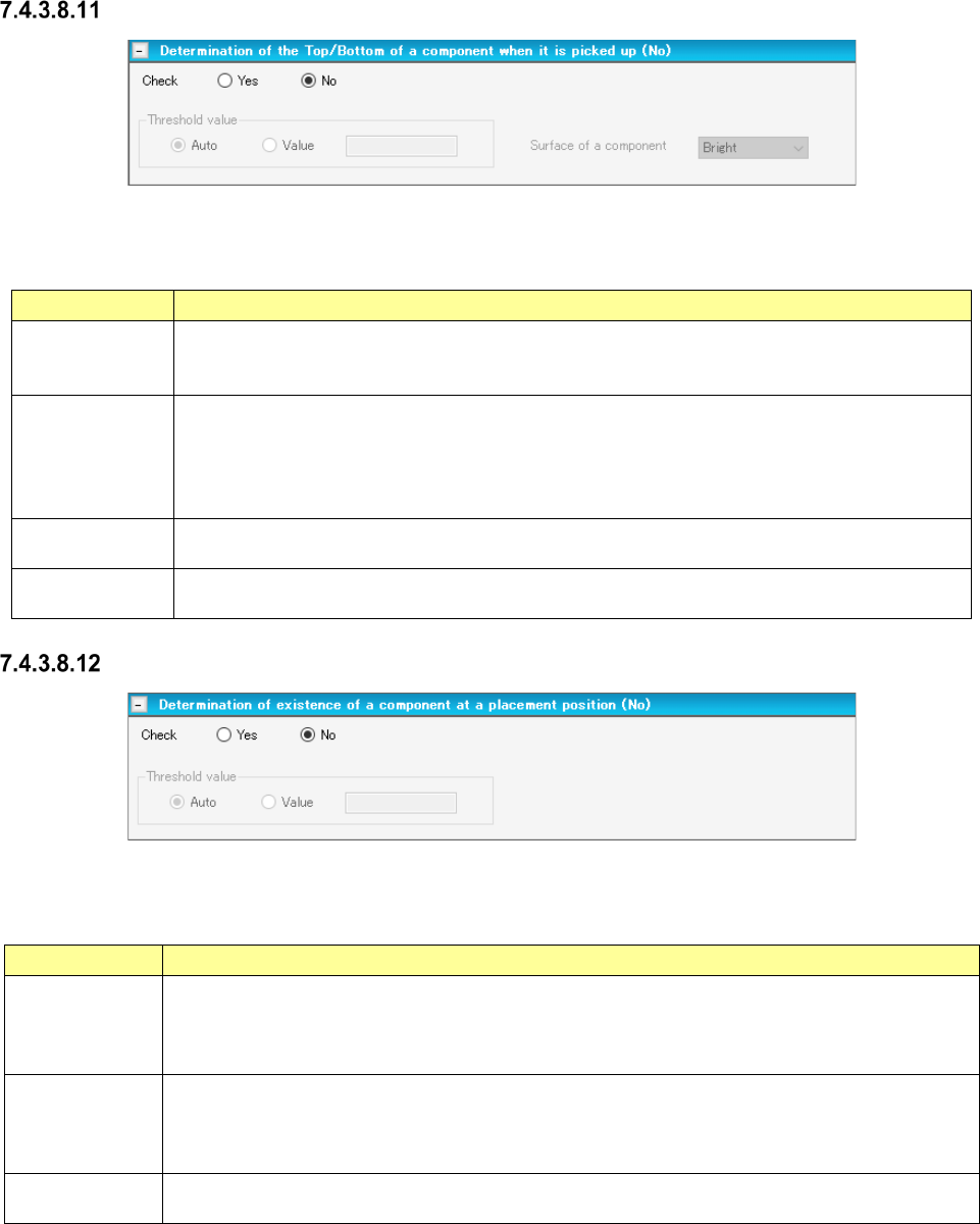
Determination of the Top/Bottom of a component when it is picked up
Figure 7.4-86 “Determination of the Top/Bottom of a component when it is picked up” screen
Table 7.4-51 Items displayed on the “Determination of the Top/Bottom of a component
when it is picked up” screen
Item Description
Check
Select with the corresponding radio button whether to decide the top/bottom of a component
when it is picked up.
The “No” radio button is selected by default.
Threshold value
Select whether a threshold value will be set automatically (Auto) or set by you (Value) with the
corresponding radio button.
The “Auto” radio button is selected by default.
When you select the “Value” radio button, the text box for entering a threshold value is
activated.
Threshold value
Value
Specify the threshold value for deciding the top/bottom of a component when it is picked up in
the range of 1 to 255. Default: 128
Surface of a
component
Select the surface of a component, “Bright” or “Dark.”
“Dark” is selected by default.
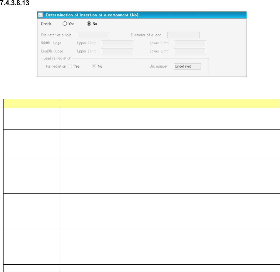
Determination of existence of a component at a placed position
Figure 7.4-87 “Determination of existence of a component at a placed position” screen
Table 7.4-52 Items displayed on the “Determination of existence of a component
at a placed position” screen
Item Description
Check
Select whether to decide if there is any component at a placement position with the corresponding
radio button.
When the length of the longer side of a component is 5.30 mm or less, the “Yes” radio button is
selected by default. When it exceeds 5.30 mm, the “No” radio button is selected by default.
Threshold value
Select whether a threshold value will be selected automatically (“Auto”) or set by you (Value) with
the corresponding radio button.
The “Auto” radio button is selected by default.
When you select the “Value” radio button, the text box for entering a threshold value is activated.
Threshold value
Value
Specify the threshold value for deciding the top/bottom of a component when it is picked up in the
range of 1 to 255. Default: 128
JaNets Instruction Manual 7. Program Editor
7-61
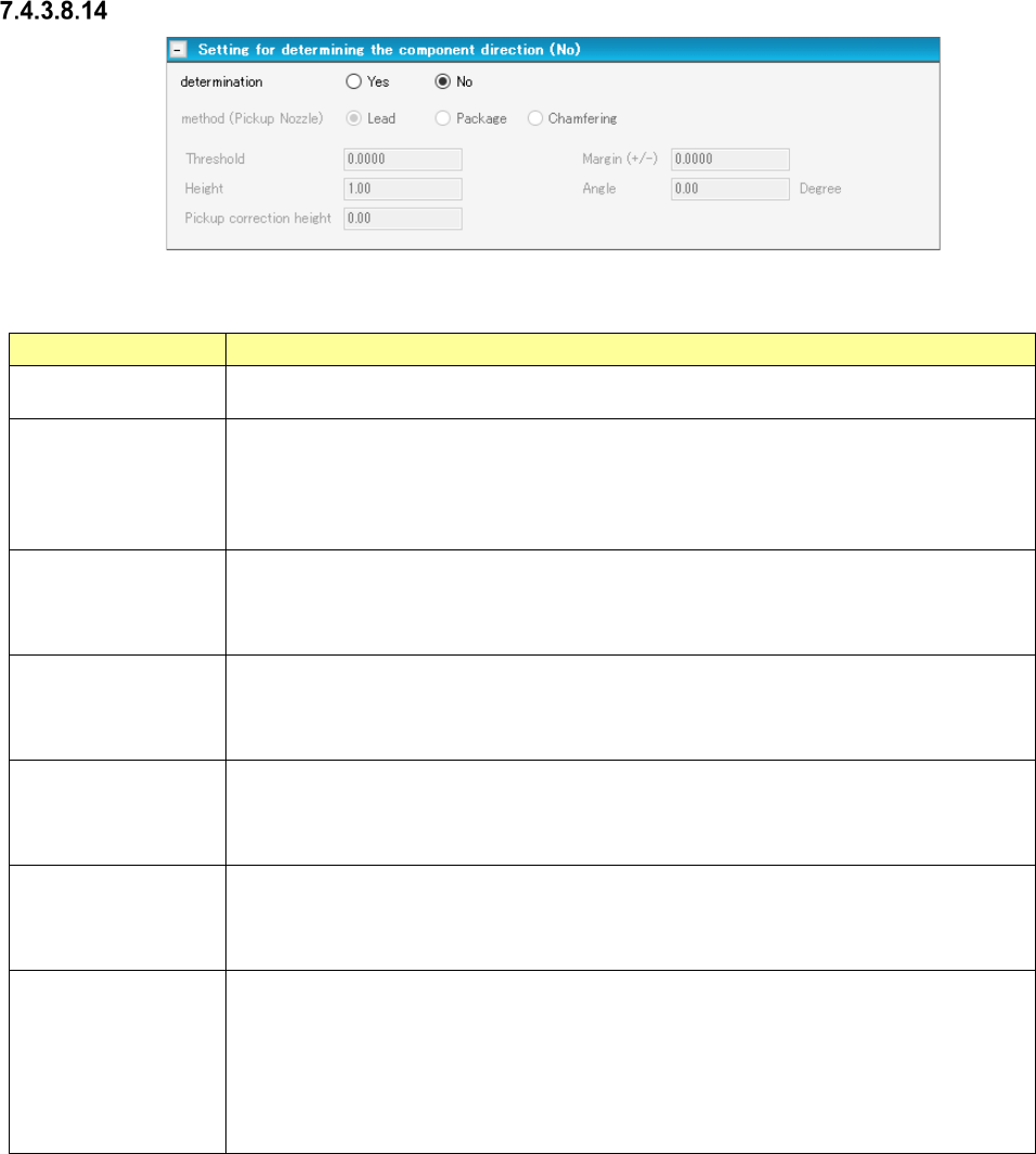
Determination of insertion of a component
Figure 7.4-88 “Determination of insertion of a component” screen
Table 7.4-53 Items displayed on the “Determination of insertion of a component” screen
Item Description
Check
Yes/No
Specify whether to decide if a component can be inserted into a board with the corre-
sponding radio button.
The “No” radio button is selected by default.
Determination of
insertion of a com-
ponent
Diameter of a hole
You can enter this field when you select the “Yes” radio button of the menu item “Check.”
Enter the diameter of a through hole of a component.
The input range is 0.01 to 15.00 mm. Note that it changes to the range of the lead diameter
to 33.5 mm when the lead diameter is set. A blank character is entered by default.
Determination of
insertion of a com-
ponent
Diameter of a lead
You can enter this field when you select the “Yes” radio button of the menu item “Check.”
Enter the diameter of a lead of a component.
The input range is 0.01 to 15.00 mm. Note that it changes to the range of 0.01 mm to the
diameter of the through hole when the through hole diameter is set. A blank character is
entered by default.
Determination of
insertion of a com-
ponent
Width Judge/Length
Judge
You can enter these fields when you select the “Yes” radio button of the menu item “Check.”
Enter the size for deciding a component.
Input range: 0.01 to 150.00 mm
The respective default values are calculated based on the through hole diameter and the
lead diameter.
Lead remediation
Yes/No
Select whether to correct a lead or not with the corresponding radio button.
You can select this menu item only when “INS Tape” is selected as the packaging style,
“MRF-S” or “MRF-L” is selected as the type, and the “Yes” radio button of this “Check” menu
item is selected.
The “No” radio button is selected by default.
Jig number
“Undefined” is selected by default.
JaNets Instruction Manual 7. Program Editor
7-62
Setting for determining the component direction
Figure 7.4-89 “Setting for determining the component direction” screen
Table 7.4-54 Items displayed on the “Setting for determining the component direction” screen
Item
Description
Determination
Yes/No
Select whether to determine the component direction with the corresponding radio button.
The “No” radio button is selected by default.
Setting for determin-
ing the component
direction
method
You can enter this field when you select the “Yes” radio button of the menu item “determi-
nation.” Select the determining method among “Lead,” “Package” and “Chamfering.”
The “Lead” radio button is selected by default.
When you select a pickup nozzle, “method (Pickup Nozzle)” is displayed as the menu item.
When you select a gripper nozzle, “method (Gripper Nozzle)” is displayed.
Setting for determin-
ing the component
direction
Threshold
You can enter this field when you select the “Yes” radio button of the menu item “determi-
nation.” Enter the reference value for deciding the direction.
Input range: - 2.0000 to 2.0000 mm Default value: 0.0000 mm
Setting for determin-
ing the component
direction
Margin (±)
You can enter this field when you select the “Yes” radio button of the menu item “determi-
nation.” Specify the margin (±) of the threshold value that does not generate any error for
the measurement result.
Input range: 0.0000 to 55.00 mm Default value: 1.00 mm
Setting for determin-
ing the component
direction
Height
You can enter this field when you select “Yes” for the menu item “determination” and
“Package” or “Chamfering” for the menu item “method.” Enter the height of a component
to be applied when a package is recognized.
Input range: 0.00 to 55.00 mm Default value: 1.00 mm
Setting for determin-
ing the component
direction
Angle
You can enter this field when you select “Yes” for the menu item “determination” and
“Chamfering” for the menu item “method.” Enter the angle to be applied when the system
decides the component direction.
Input range: - 90.00 to 90.00 degrees Default value: 0.00 degrees
Setting for determin-
ing the component
direction
Pickup correction
height
You can enter this field when you select “Yes” for the menu item “determination” and “Lead”
or “Package” for the menu item “method.”
However, you cannot enter this field when you select a gripper nozzle regardless of the
setting of the menu item “method.”
Enter the component pick-up correction height to be applied when the system decides the
component direction.
Input range: 0.00 to 55.00 mm Default value: “Component height” – 0.3 mm