JANETS_INM.pdf - 第271页
JaNets In structio n Manual 7. Program Editor 7- 64 Component insertion error detecting f unction (JM - 10 0 S eries ) Figure 7.4 - 92 “ Component inserti on error detec ting function ” (JM -100 S eries ) screen T able 7…
JaNets Instruction Manual 7. Program Editor
7-63
Component insertion error detecting function (JM-20 Series)
Figure 7.4-90 “Component insertion error detecting function” (JM-20 series) screen
Table 7.4-55 Menu items displayed on the
“Component insertion error detecting function” (JM-20 Series) screen
Item Description
Check
Yes/No
Select whether to detect a component insertion error with the JM-20 with the corresponding
radio button.
You can select this menu item only when “Insertion component” or “INS electrolytic capacitor”
is selected as the component type.
The “No” radio button is selected by default.
Normal judgment
range
Set the normality judgment range based on the data obtained with the JM-20.
A total of the torque ratio in normal operation and the value specified here becomes the upper
limit of this range, while the value specified here subtracted from the torque ratio becomes
the lower limit of this range.
Data obtaining
condition
Shows the torque ratio obtaining condition. “Not obtained” or “Obtained” is displayed here.
Component insertion error detecting function (JM-10 Series)
Figure 7.4-91 “Component insertion error detecting function” (JM-10 Series) screen
Table 7.4-56 Menu items displayed on the
“Component insertion error detecting function” (JM-10 Series) screen
Item
Description
Check
Yes/No
Select whether to detect a component insertion error with the JM-10 with the corresponding
radio button.
You can select this menu item only when “Insertion component” or “INS electrolytic capaci-
tor” is selected as the component type.
The “No” radio button is selected by default.
Normal judgment
range
Set the normality judgment range based on the data obtained with the JM-10.
A total of the torque ratio in normal operation and the value specified here becomes the
upper limit of this range, while the value specified here subtracted from the torque ratio
becomes the lower limit of this range.
Data obtaining
condition
Shows the torque ratio obtaining condition. “Not obtained” or “Obtained” is displayed here.
JaNets Instruction Manual 7. Program Editor
7-64
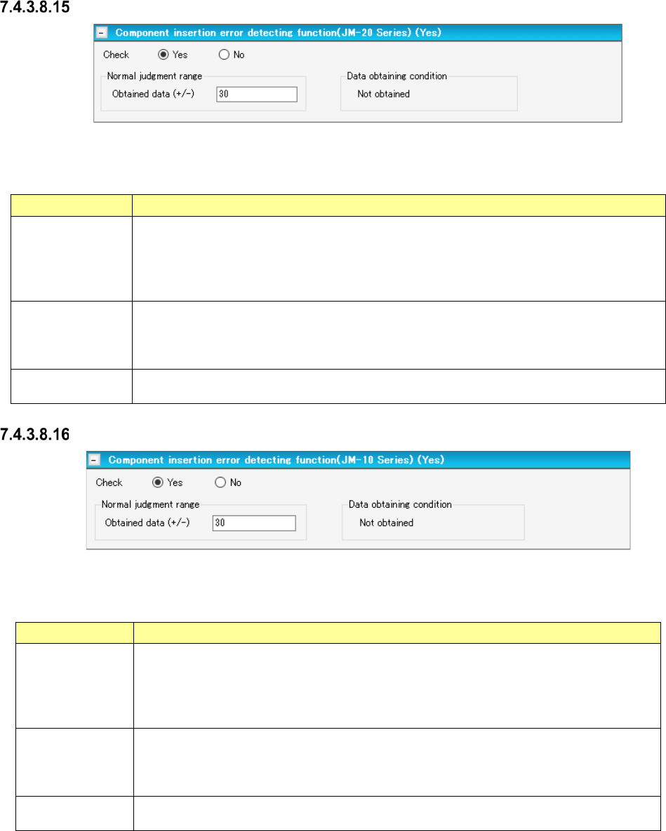
Component insertion error detecting function (JM-100 Series)
Figure 7.4-92 “Component insertion error detecting function” (JM-100 Series) screen
Table 7.4-57 Menu items displayed on the
“Component insertion error detecting function” (JM-100 Series) screen
Item
Description
Check
Yes/No
Select whether to detect a component insertion error with the JM-10 with the corresponding
radio button.
You can select this menu item only when “Insertion component” or “INS electrolytic capaci-
tor” is selected as the component type.
The “No” radio button is selected by default.
Normal judgment
range
Set the normality judgment range based on the data obtained with the JM-10.
A total of the torque ratio in normal operation and the value specified here becomes the
upper limit of this range, while the value specified here subtracted from the torque ratio
becomes the lower limit of this range.
Data obtaining
condition
Shows the torque ratio obtaining condition. “Not obtained” or “Obtained” is displayed here.
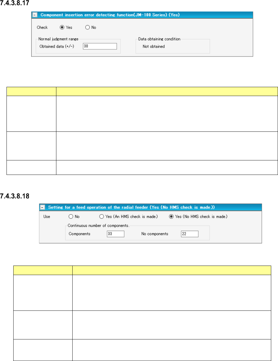
Setting for a feed operation of the radial feeder
Figure 7.4-93 “Setting for a feed operation of the radial feeder” screen
Table 7.4-58 Items displayed on the “Setting for a feed operation of the radial feeder” screen screen
Item Description
Use
No/Yes (An HMS
check is made)
Yes (No HMS check
is made)
You can set this menu item when
- the component type is “Insertion component” or “INS electrolytic capacitor”
-“INS Tape” is selected, and the type is “MRF-S” or “MRF-L.”
Select whether to perform a feed operation or not among “No” (default), “Yes (An
HMS check is made)” and “Yes (No HMS check is made).”
Continuous number of
components – Com-
ponent
Specify the number of components from a missing component position to the next
missing component position.
Default: 1
Input range: 1 – 9999
Continuous number of
components –
No components
Set the number of missing components.
Default: 1
Input range: 1 – 255
JaNets Instruction Manual 7. Program Editor
7-65
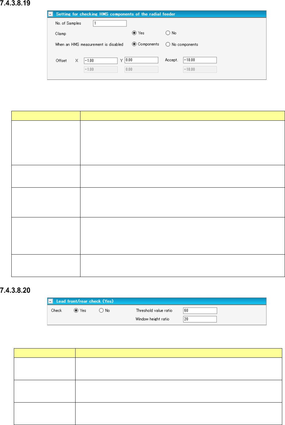
Setting for checking HMS components of the radial feeder
Figure 7.4-94 “Setting for checking HMS components of the radial feeder” screen
Table 7.4-59 Check items displayed on the
“Setting for checking HMS components of the radial feeder” screen
Item Description
No. of Samples
You can set this menu item when
- the component type is “Insertion component” or “INS electrolytic capacitor”
- “INS Tape” is selected, and the type is “MRF-S” or “MRF-L.”
Specify the number of positions to be measured.
Default: 1
Input range: 1 to 2
Clamp
Yes/No
Select whether to check if there is any component with the HMS while the board
is being clamped.
Select “Yes” (default) or “No.”
When an HMS
measurement is disabled
Components/No
components
Select the component existence state to be applied if the HMS fails to measure.
Select “Components” (default) or “No components.”
Offset X, Y
Specify an offset value viewed from the component pick-up position.
Specify an offset value for each sample to be checked.
Default: X = - 1.00 mm, Y = 0.00 mm
Input range: X = ± Package dimension X
Y = ± Package dimension Y
Accept.
Specify a value for deciding if there is any component.
Default: - 18.00 mm
Input range: ± 35.00 mm
Lead front/rear check
Figure 7.4-95 “Lead front/rear check” screen
Table 7.4-60 Check items displayed on the “Lead front/rear check” screen
Item Description
Check
This menu item is activated only when an RX-7 series is used and the “Lead
component” is selected as the component type.
The “No” radio button is selected by default.
Threshold value ratio
Specify the threshold value ratio.
Default: 60 %
Input range: 1 to 100
Window height ratio
Specify the window height ratio.
Default: 20 %
Input range: 1 – 100