JANETS_INM.pdf - 第273页
JaNets In structio n Manual 7. Program Editor 7- 66 V ision Main screen for ent eri ng the vision component conditions W hen you sel ect “ Component D ata ” fro m the tree v iew of the “ Basi c Se tting s ” screen, an d …
JaNets Instruction Manual 7. Program Editor
7-65
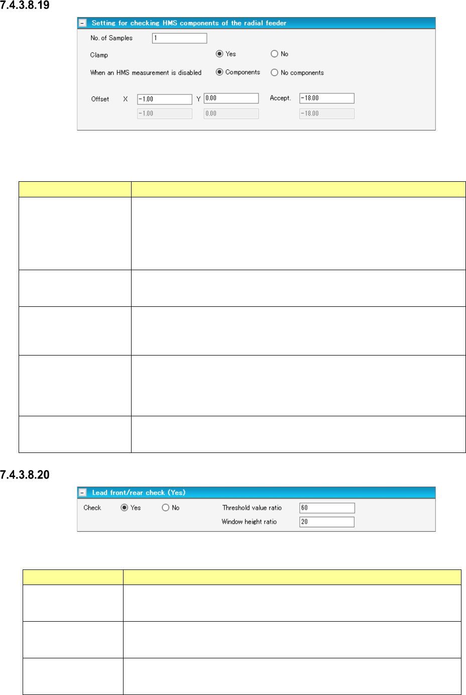
Setting for checking HMS components of the radial feeder
Figure 7.4-94 “Setting for checking HMS components of the radial feeder” screen
Table 7.4-59 Check items displayed on the
“Setting for checking HMS components of the radial feeder” screen
Item Description
No. of Samples
You can set this menu item when
- the component type is “Insertion component” or “INS electrolytic capacitor”
- “INS Tape” is selected, and the type is “MRF-S” or “MRF-L.”
Specify the number of positions to be measured.
Default: 1
Input range: 1 to 2
Clamp
Yes/No
Select whether to check if there is any component with the HMS while the board
is being clamped.
Select “Yes” (default) or “No.”
When an HMS
measurement is disabled
Components/No
components
Select the component existence state to be applied if the HMS fails to measure.
Select “Components” (default) or “No components.”
Offset X, Y
Specify an offset value viewed from the component pick-up position.
Specify an offset value for each sample to be checked.
Default: X = - 1.00 mm, Y = 0.00 mm
Input range: X = ± Package dimension X
Y = ± Package dimension Y
Accept.
Specify a value for deciding if there is any component.
Default: - 18.00 mm
Input range: ± 35.00 mm
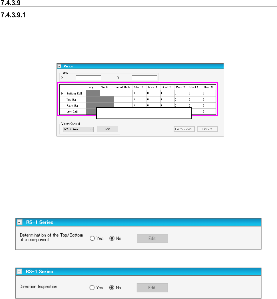
Lead front/rear check
Figure 7.4-95 “Lead front/rear check” screen
Table 7.4-60 Check items displayed on the “Lead front/rear check” screen
Item Description
Check
This menu item is activated only when an RX-7 series is used and the “Lead
component” is selected as the component type.
The “No” radio button is selected by default.
Threshold value ratio
Specify the threshold value ratio.
Default: 60 %
Input range: 1 to 100
Window height ratio
Specify the window height ratio.
Default: 20 %
Input range: 1 – 100
JaNets Instruction Manual 7. Program Editor
7-66
Vision
Main screen for entering the vision component conditions
When you select “Component Data” from the tree view of the “Basic Settings” screen, and then
“Vision,” the main screen for a vision component appears. When you change the setting of the
“Leads on” field on the “CONN” screen, data on the bottom leads and that on the top leads are
replaced with each other. Set the length and the width of a lead, and the number of leads on this
screen.
Figure 7.4-96 Main screen for the Top/Bottom/Left/Right Lead Data of a vision component
On the upper panel of the main screen for a vision component, you have to set the length of a lead,
the width of a lead, the number of leads and so on. The menu items such as the lead length, the
lead width and the number of leads you can enter are changed depending on the “Component
Type” you selected on the “Basic Settings” screen of the component data.
When an RS-1 series is included in the production line, the RS-1 series panel that allows you to
enter data unique to the RS-1 series appears on the screen.
Figure 7.4-97 RS-1 Series panel screen (when a chip is selected)
Figure 7.4-98 RS-1 Series panel screen (when a BGA or FBGA component is selected)
Data is displayed at this position.
JaNets Instruction Manual 7. Program Editor
7-67
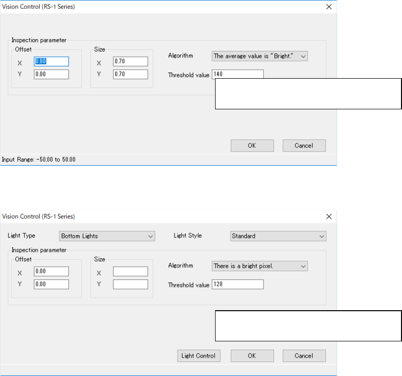
When you press the <Edit> button, the following screen appears.
Figure 7.4-99 Screen for entering data for determining the side of a component,
front or rear (in case of a chip)
Figure 7.4-100 Screen for entering data for inspecting the direction of a component
(in case of a BGA or FBGA component)
On the lower panel of the main screen for a vision component, you have to set the recognition type
and the base style of each component type mainly. The menu items to be displayed vary de-
pending on the component type. The example is shown below.
Specify recognition parameters for deciding
the side of a component, front or rear.
Specify recognition parameters for inspect-
ing the direction of a component