JANETS_INM.pdf - 第274页
JaNets In structio n Manual 7. Program Editor 7- 67 When you pres s the <Ed it> button, t he following scr een appear s. Figure 7.4 - 99 Screen for entering da ta for determ ining the side of a component, front or …
JaNets Instruction Manual 7. Program Editor
7-66
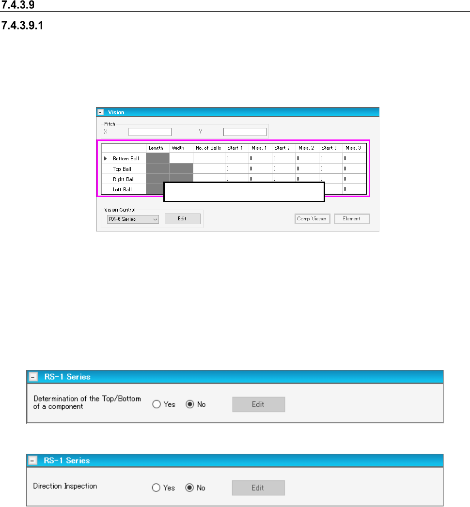
Vision
Main screen for entering the vision component conditions
When you select “Component Data” from the tree view of the “Basic Settings” screen, and then
“Vision,” the main screen for a vision component appears. When you change the setting of the
“Leads on” field on the “CONN” screen, data on the bottom leads and that on the top leads are
replaced with each other. Set the length and the width of a lead, and the number of leads on this
screen.
Figure 7.4-96 Main screen for the Top/Bottom/Left/Right Lead Data of a vision component
On the upper panel of the main screen for a vision component, you have to set the length of a lead,
the width of a lead, the number of leads and so on. The menu items such as the lead length, the
lead width and the number of leads you can enter are changed depending on the “Component
Type” you selected on the “Basic Settings” screen of the component data.
When an RS-1 series is included in the production line, the RS-1 series panel that allows you to
enter data unique to the RS-1 series appears on the screen.
Figure 7.4-97 RS-1 Series panel screen (when a chip is selected)
Figure 7.4-98 RS-1 Series panel screen (when a BGA or FBGA component is selected)
Data is displayed at this position.
JaNets Instruction Manual 7. Program Editor
7-67
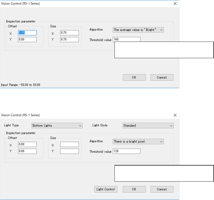
When you press the <Edit> button, the following screen appears.
Figure 7.4-99 Screen for entering data for determining the side of a component,
front or rear (in case of a chip)
Figure 7.4-100 Screen for entering data for inspecting the direction of a component
(in case of a BGA or FBGA component)
On the lower panel of the main screen for a vision component, you have to set the recognition type
and the base style of each component type mainly. The menu items to be displayed vary de-
pending on the component type. The example is shown below.
Specify recognition parameters for deciding
the side of a component, front or rear.
Specify recognition parameters for inspect-
ing the direction of a component
JaNets Instruction Manual 7. Program Editor
7-68
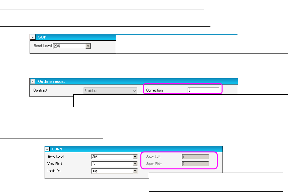
For components: SOP, HSOP, SOJ, TSOP, TSOP2, QFP, PLCC, PQFP (BQFP), J-lead socket
(SKT-J), gull-wing socket (SKT-G) and socket with a bumper (SKT-B):
The following example shows the screen for setting an SOP component.
Figure 7.4-101 SOP item setting screen
For an outline-recognized component:
Figure 7.4-102 Outline-recognized component setting screen
For a unidirectional lead connector:
Figure 7.4-103 Unidirectional lead connector setting screen
Select the level for detecting a bent lead.
* The “Bend Level” should also be set on the following screens.
Enter a correction value for the brightness when light is turned on a component.
Enter the number of leads on the upper left side
and that on the upper right side.