JANETS_INM.pdf - 第277页
JaNets In structio n Manual 7. Program Editor 7- 70 “ Element Data ” setting screen Set the lead l ength , lead width , pitch between l eads and lead as sign ment of a lead comp onent on this screen. Figure 7.4 - 108 “ E…

JaNets Instruction Manual 7. Program Editor
7-69
For a bi-directional lead connector or a Z lead connector
Figure 7.4-104 Bi-directional lead connector setting screen
For an extended-lead connector:
Figure 7.4-105 Extended-lead connector setting screen
For a QFN:
Figure 7.4-106 QFN setting screen
For a BGA/FBGA
Figure 7.4-107 BGA setting screen
Enter the number of leads on the upper left side, that on the upper right
side, that on the lower left side and that on the lower right side.
Enter the rightmost lead
position, X and Y.
Select the corre-
sponding bit
map pattern.
Select the corresponding bit
map pattern.
Ball Pattern: When you select “Peripheral BGA,” enter the
number of lines in the “Peripheral Rows” field.
JaNets Instruction Manual 7. Program Editor
7-70
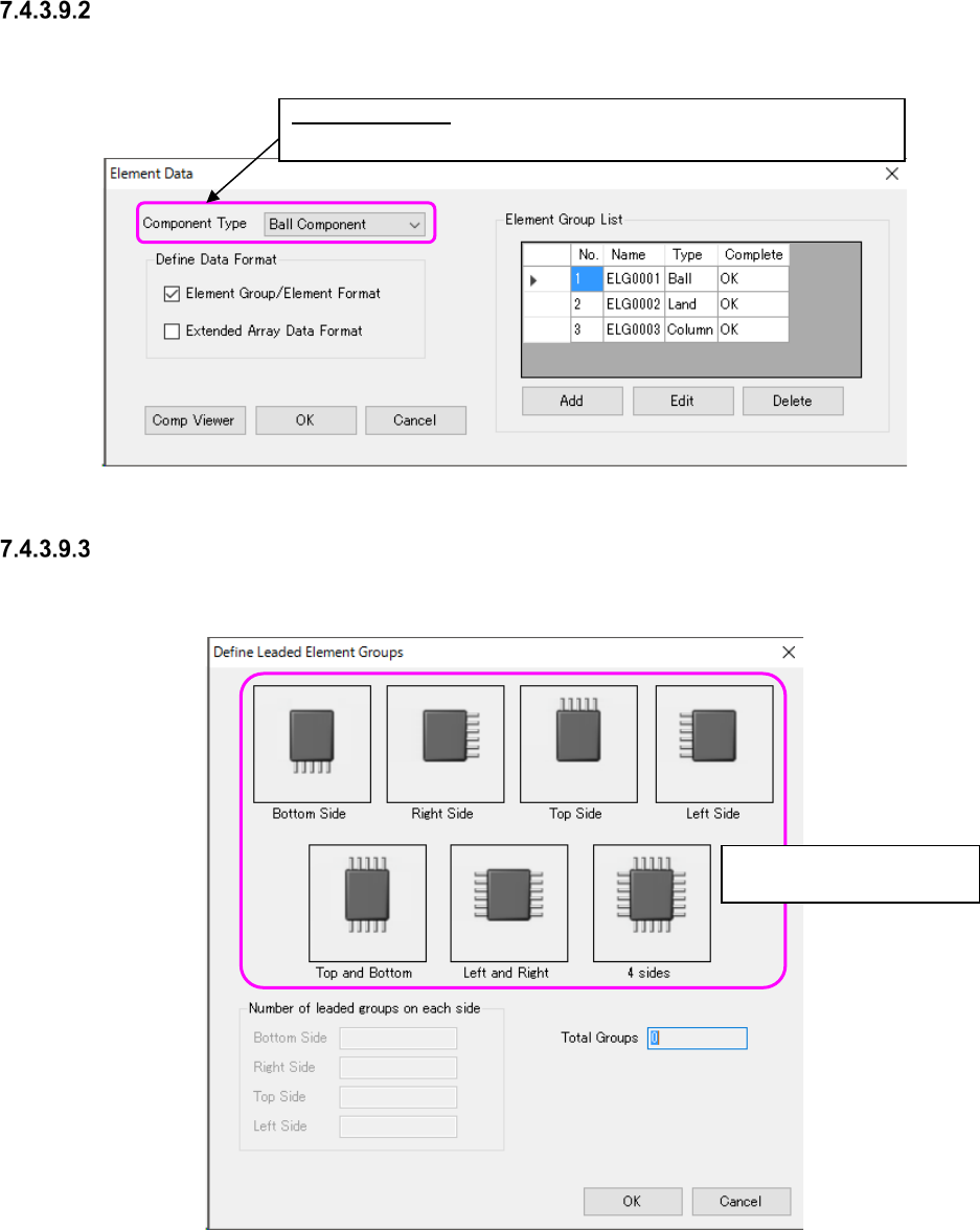
“Element Data” setting screen
Set the lead length, lead width, pitch between leads and lead assignment of a lead component on
this screen.
Figure 7.4-108 “Element Data” screen
“Define Leaded Element Groups” screen
On this screen, you can set data such as the number of element groups quickly.
Figure 7.4-109 “Define Leaded Element Groups” screen
Component Type: Select one of the following: “Lead Component,” Ball
Component” and “Outline Component.”
Select the corresponding
bit map pattern.
JaNets Instruction Manual 7. Program Editor
7-71
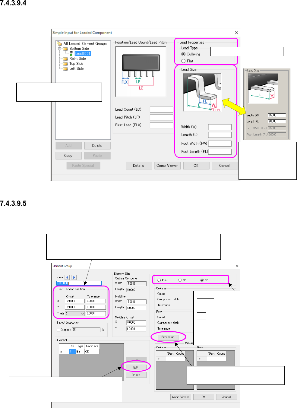
“Simple Input for Leaded Component” screen
This screen allows you to set data such as the number of leads, the lead pitch, the lead length and
the lead width of each element group easily by showing the bit map.
Figure 7.4-110 “Simple Input for Leaded Component” screen
“Element Group” setting screen
This screen allows you to set the details such as the element position, the number of elements,
and the pitch between the consecutive elements of each element group.
Figure 7.4-111 “Element Group” screen
Select the lead type here.
Enter the coordinates of the center of the tip of the reference lead
viewed from that of a component.
* The input range is within the outer dimensions of a component.
Point: Specify the side, corner
and mark.
1D: Specify a lead.
2D: Specify a ball/land.
* When you switch the radio
button, the input items are al-
so switched on the screen.
When an element is registered, this <Edit>
button is enabled, and the system allows
you to make the detailed settings.
Set the expansion data. It is valid for
3010/3020/3020R/3020V/3020VR.
Execute the element group set-
ting selected in this tree view.
The screen is
switched to another
one according to the
lead type you se-
lected above.