JANETS_INM.pdf - 第286页
JaNets In structio n Manual 7. Program Editor 7- 79 (6) Extended - array ele ment This scree n shows how an ext ended - array element is ass igned . Figure 7.4 - 122 Screen for displ aying an ext ended - a rray elemen t …
JaNets Instruction Manual 7. Program Editor
7-78
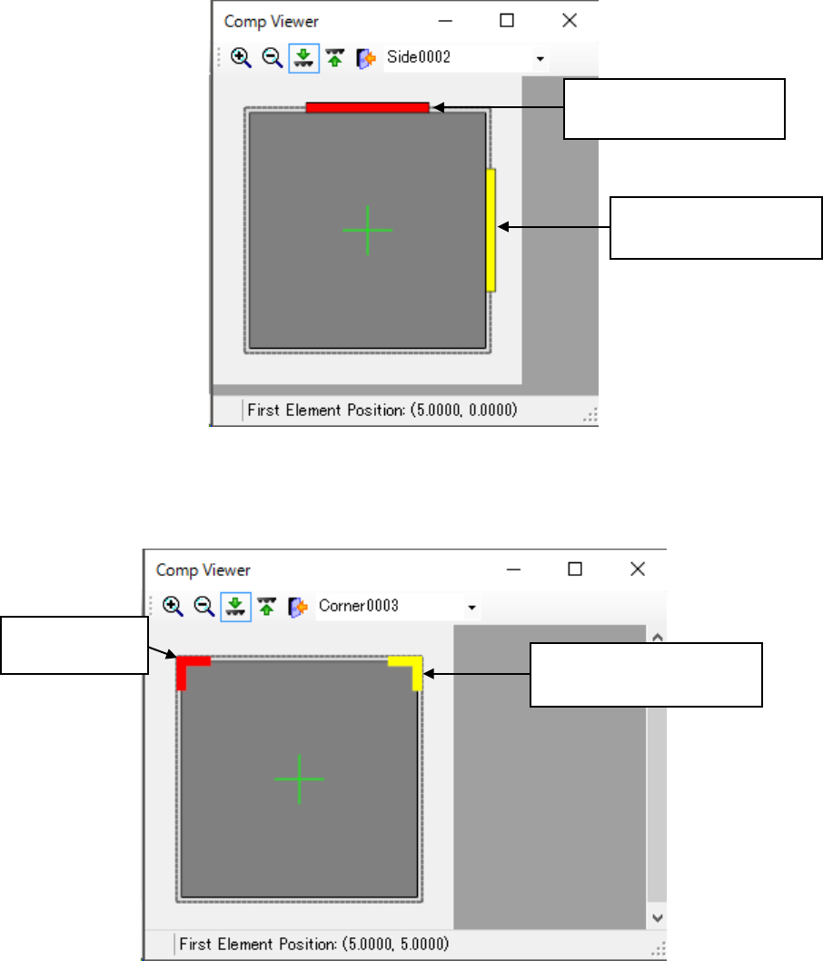
(4) Side element
This screen shows how a side element is assigned.
Figure 7.4-120 Screen for displaying a side element
(5) Corner element
This screen shows how a corner element is assigned.
Figure 7.4-121 Screen for displaying a corner element
Selected side element:
shown with a yellow line.
Side element not selected:
shown with a red line.
Corner element
not selected:
Selected corner element:
shown in yellow.
JaNets Instruction Manual 7. Program Editor
7-79
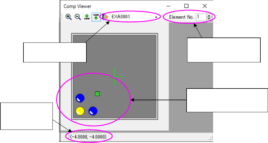
(6) Extended-array element
This screen shows how an extended-array element is assigned.
Figure 7.4-122 Screen for displaying an extended-array element
Displays the extended
array group list
Displays the location no.
and total count of the se-
lected element
Displays the coor-
dinates of the
selected element
Selected elements are dis-
played in yellow while ele-
ments not selected are in blue.
JaNets Instruction Manual 7. Program Editor
7-80
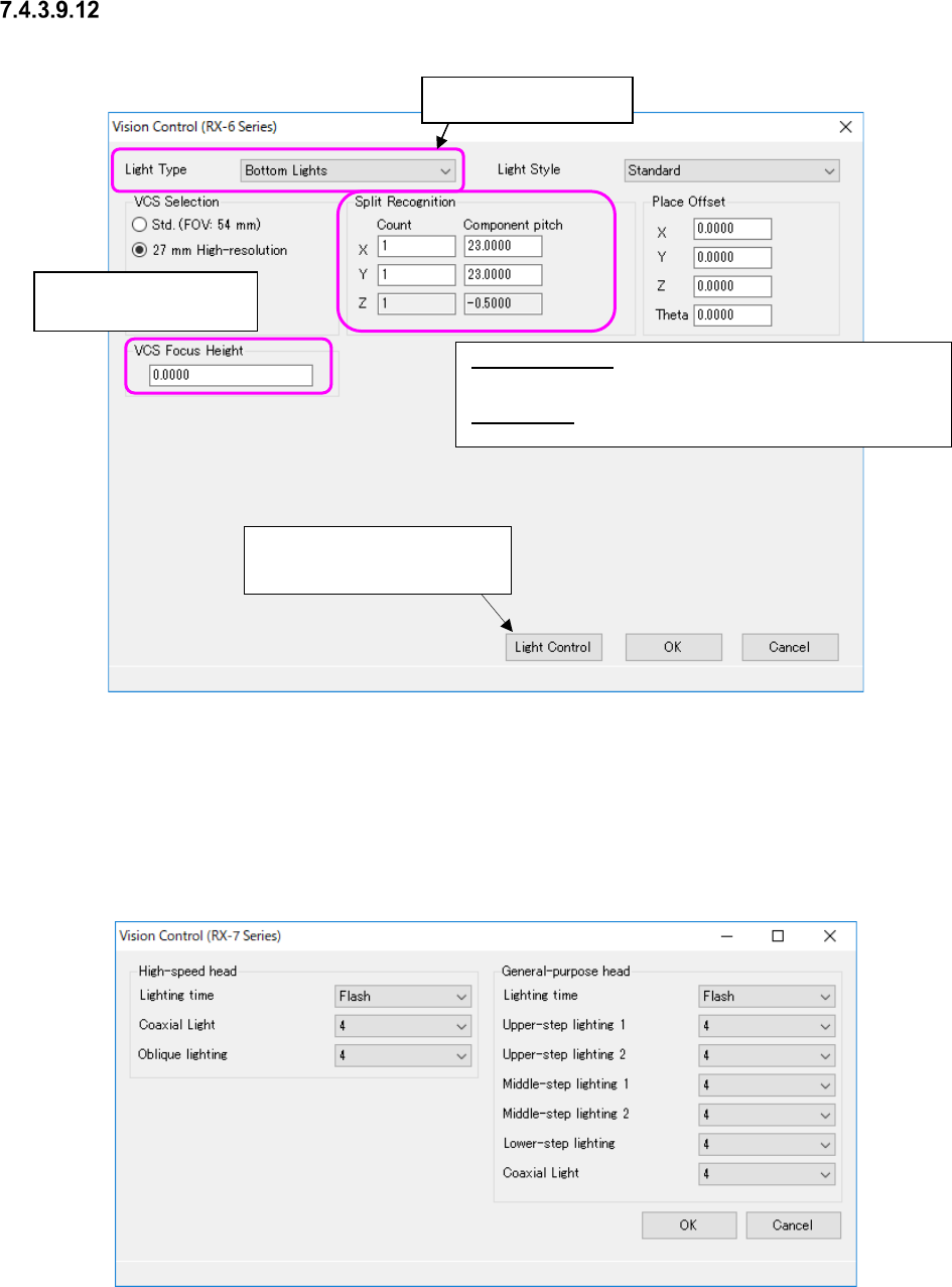
“Vision Control” data setting screen
Figure 7.4-123 “Vision Control” data screen (RX-6)
* Refer to the Machine Specifications or Instruction Manual of your model for “VCS you can se-
lect.”
When you select “RX-7 series” from the “Vision Control” pull-down menu and press the <Edit>
button, the screen like one shown below appears.
Figure 7.4-124 “Vision Control” data screen (RX-7 Series)
Split Recognition: The range of a number to be entered in the
“Count” field is from 1 to 2 in case of “X,” 1 to 3 in case of “Y, ”
and 1 in case of “Z.”
Place Offset: Enter an offset of a component to be applied when
it is placed on a board.
Enter the height to be
recognized with a VCS.
This button proceeds to the
“Light Control” data screen.
Select the light style.