JANETS_INM.pdf - 第287页
JaNets In structio n Manual 7. Program Editor 7- 80 “ Vision Control ” data setting screen Figure 7.4 - 123 “ Vision Control ” data sc reen (RX - 6) * Refer to the Mach ine Sp ecific ations or I nstructio n Manual o f yo…
JaNets Instruction Manual 7. Program Editor
7-79
(6) Extended-array element
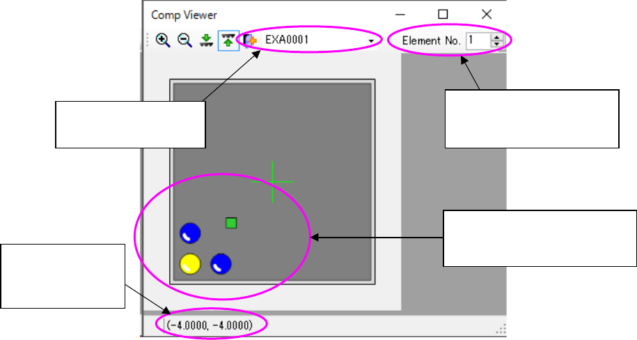
This screen shows how an extended-array element is assigned.
Figure 7.4-122 Screen for displaying an extended-array element
Displays the extended
array group list
Displays the location no.
and total count of the se-
lected element
Displays the coor-
dinates of the
selected element
Selected elements are dis-
played in yellow while ele-
ments not selected are in blue.
JaNets Instruction Manual 7. Program Editor
7-80
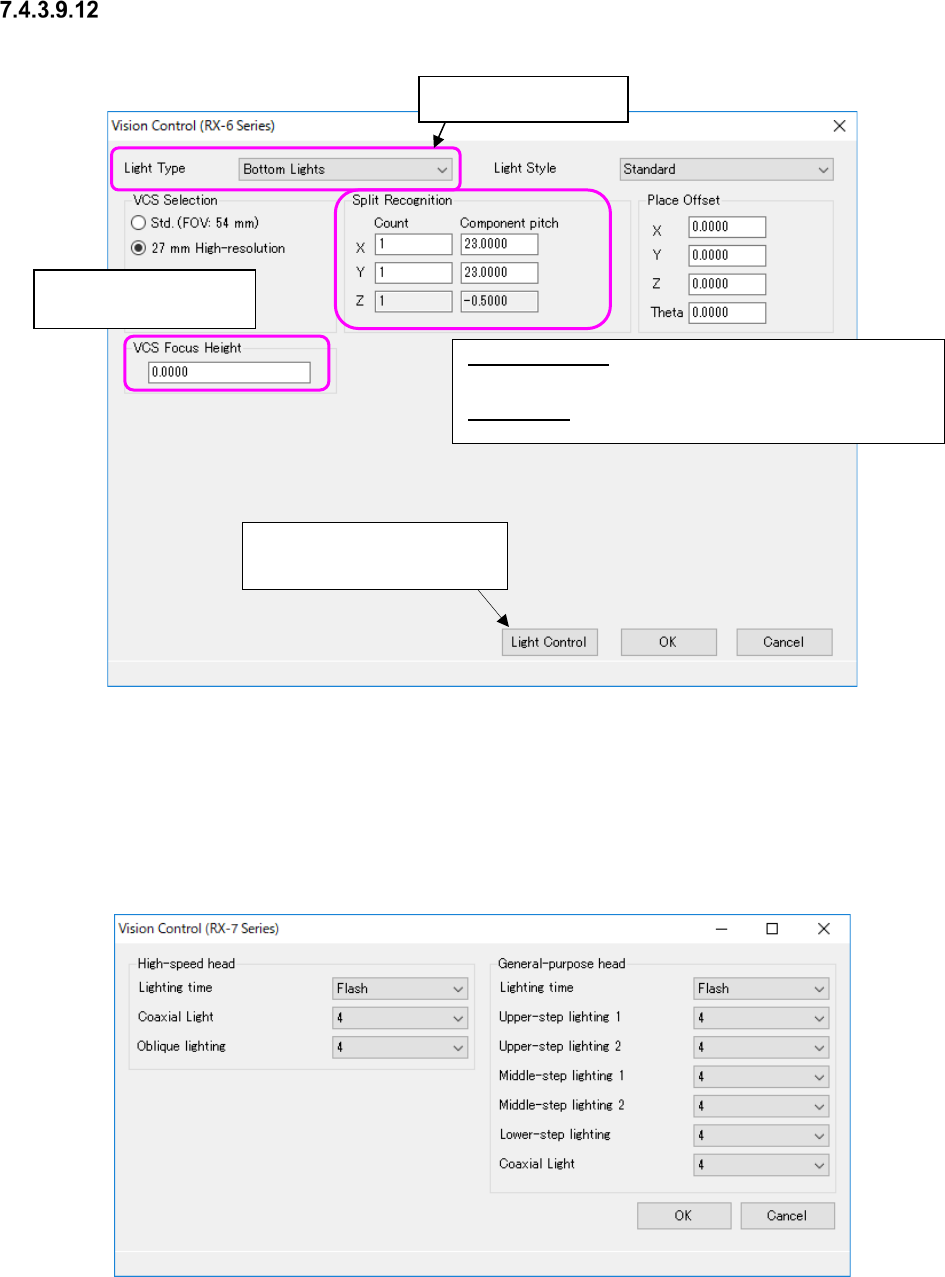
“Vision Control” data setting screen
Figure 7.4-123 “Vision Control” data screen (RX-6)
* Refer to the Machine Specifications or Instruction Manual of your model for “VCS you can se-
lect.”
When you select “RX-7 series” from the “Vision Control” pull-down menu and press the <Edit>
button, the screen like one shown below appears.
Figure 7.4-124 “Vision Control” data screen (RX-7 Series)
Split Recognition: The range of a number to be entered in the
“Count” field is from 1 to 2 in case of “X,” 1 to 3 in case of “Y, ”
and 1 in case of “Z.”
Place Offset: Enter an offset of a component to be applied when
it is placed on a board.
Enter the height to be
recognized with a VCS.
This button proceeds to the
“Light Control” data screen.
Select the light style.
JaNets Instruction Manual 7. Program Editor
7-81
Set the following items on the “Vision Control (RX-7 series)” screen.
Table 7.4-61 Vision control data screen (RX-7 Series) items
Head
Item
Description
High-speed head
Lighting time
Select “At all times” or “Flash.” “Flash” is initially selected
Coaxial Light
Select the brightness of the light in the range of 0 to 8.
If the Component shape type is a chip, “2”
is set by default.
Otherwise, “4” is set by default.
Oblique Lighting
Select the brightness of the light in the range of 0 to 8.
If the Component shape type is a chip, “2”
is set by default.
Otherwise, “4” is set by default.
General-purpose
head
Lighting time
Select “At all times” or “Flash.” “Flash” is initially selected
Upper-step Lighting 1
Select the brightness of the light in the range of 0 to 8.
The initial value is “4.”
Upper-step Lighting 2
Select the brightness of the light in the range of 0 to 8.
The initial value is “4.”
Middle-step Lighting 1 Select the brightness of the light in the range of 0 to 8.
The initial value is “4.”
Middle-step Lighting 2
Select the brightness of the light in the range of 0 to 8.
The initial value is “4.”
Lower-step Lighting 1 Select the brightness of the light in the range of 0 to 8.
The initial value is “4.”
Coaxial Light
Select the brightness of the light in the range of 0 to 8.
The initial value is “4.”
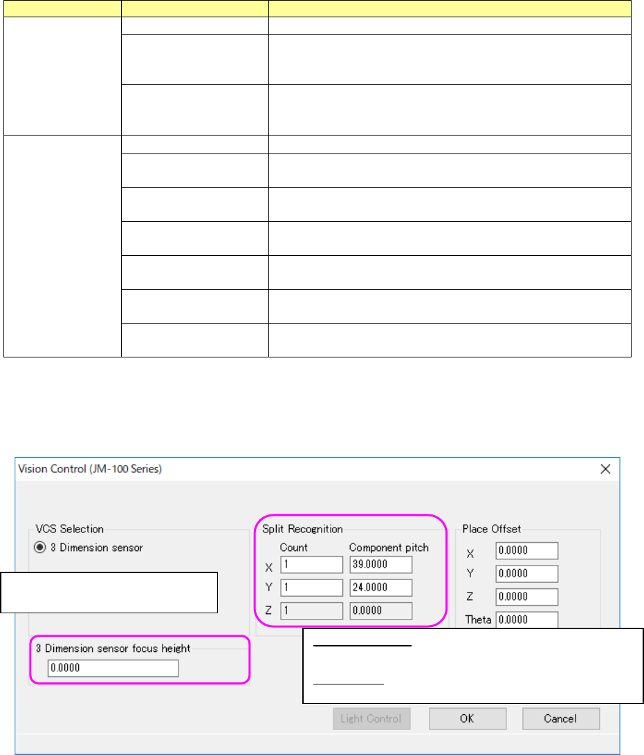
When you select “JM-100” from the “Vision Control” pull-down menu and press the <Edit> button,
the screen like one shown below appears.
Figure 7.4-125 “Vision Control” data screen (JM-100 Series)
Split Recognition: The range of a number to be entered in the
“Count” field is from 1 to 2 in case of “X,” 1 to 3 in case of “Y, ”
and 1 in case of “Z.”
Place Offset: Enter an offset of a component to be applied when
it is placed on a board.
Enter the height to be recognized
with 3D sensor.