JANETS_INM.pdf - 第289页
JaNets In structio n Manual 7. Program Editor 7- 82 V ision component RX - 7 series data When you put a ch eckm ark in the “ Use ” check box o f the “ RX - 7 series Vis i o n ” colu mn, v ision data is validated, and the…
JaNets Instruction Manual 7. Program Editor
7-81
Set the following items on the “Vision Control (RX-7 series)” screen.
Table 7.4-61 Vision control data screen (RX-7 Series) items
Head
Item
Description
High-speed head
Lighting time
Select “At all times” or “Flash.” “Flash” is initially selected
Coaxial Light
Select the brightness of the light in the range of 0 to 8.
If the Component shape type is a chip, “2”
is set by default.
Otherwise, “4” is set by default.
Oblique Lighting
Select the brightness of the light in the range of 0 to 8.
If the Component shape type is a chip, “2”
is set by default.
Otherwise, “4” is set by default.
General-purpose
head
Lighting time
Select “At all times” or “Flash.” “Flash” is initially selected
Upper-step Lighting 1
Select the brightness of the light in the range of 0 to 8.
The initial value is “4.”
Upper-step Lighting 2
Select the brightness of the light in the range of 0 to 8.
The initial value is “4.”
Middle-step Lighting 1 Select the brightness of the light in the range of 0 to 8.
The initial value is “4.”
Middle-step Lighting 2
Select the brightness of the light in the range of 0 to 8.
The initial value is “4.”
Lower-step Lighting 1 Select the brightness of the light in the range of 0 to 8.
The initial value is “4.”
Coaxial Light
Select the brightness of the light in the range of 0 to 8.
The initial value is “4.”
When you select “JM-100” from the “Vision Control” pull-down menu and press the <Edit> button,
the screen like one shown below appears.
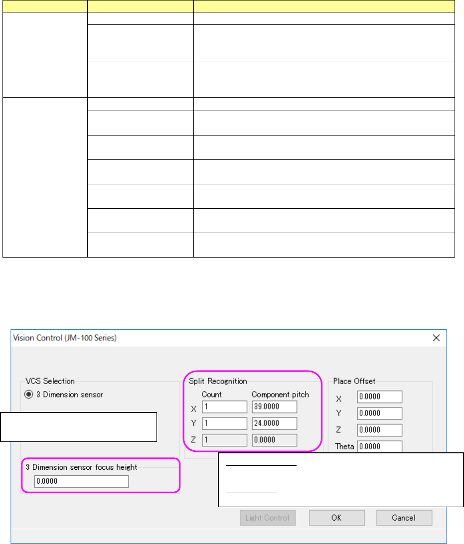
Figure 7.4-125 “Vision Control” data screen (JM-100 Series)
Split Recognition: The range of a number to be entered in the
“Count” field is from 1 to 2 in case of “X,” 1 to 3 in case of “Y, ”
and 1 in case of “Z.”
Place Offset: Enter an offset of a component to be applied when
it is placed on a board.
Enter the height to be recognized
with 3D sensor.
JaNets Instruction Manual 7. Program Editor
7-82
Vision component RX-7 series data
When you put a checkmark in the “Use” check box of the “RX-7 series Vision” column, vision data
is validated, and the “RX-7 series Vision” panel is displayed on the screen.
When you press the <RX-7 series Option> button, you can set the options for recognizing a
component with an RX-7 series also.
To set RX-7 vision data only, you do not have to make any settings such as the pitch and the
number of leads/balls on the “Vision” panel.
To set the RX-7 series vision data, use the <Edit> button.
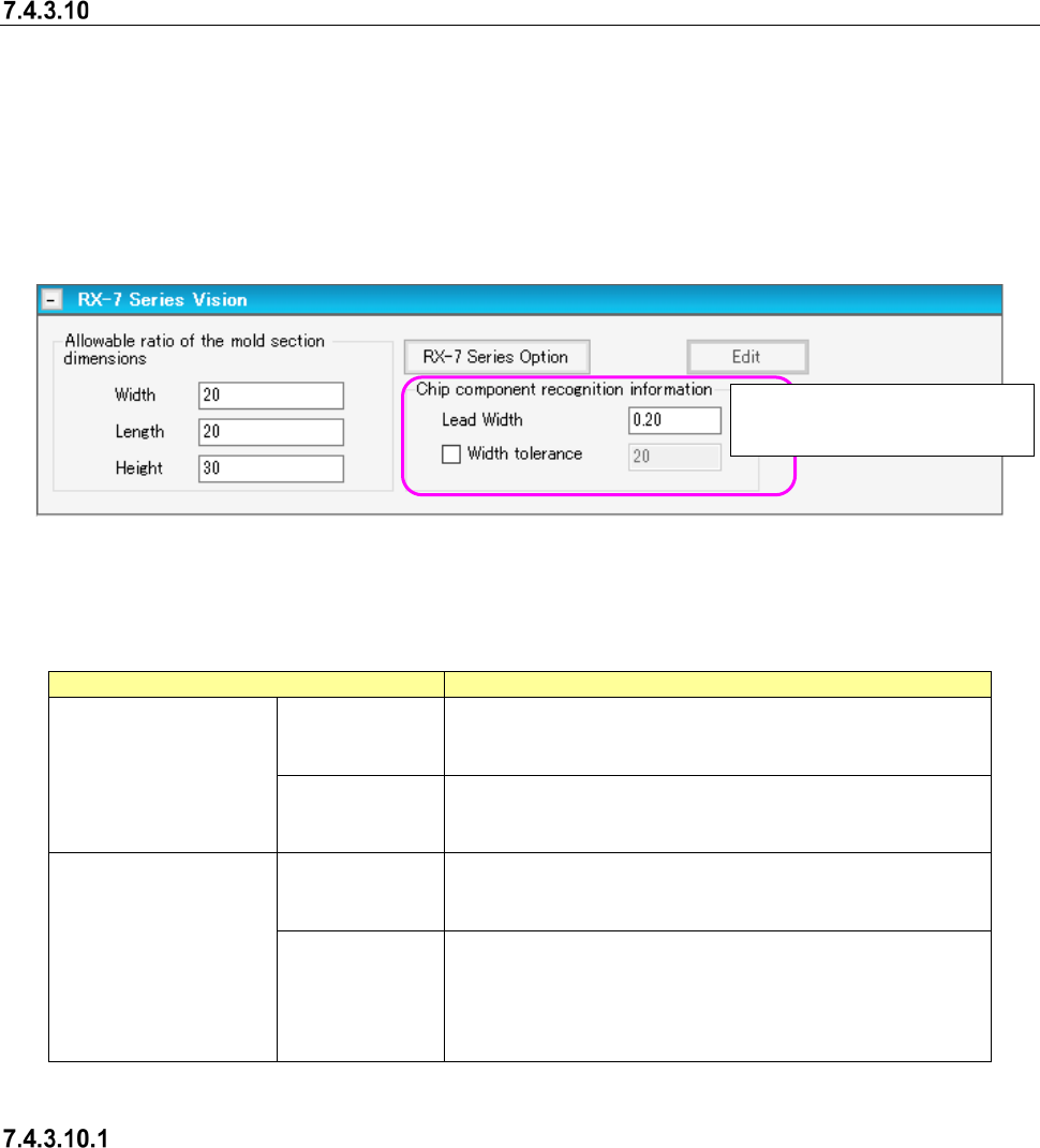
Figure 7.4-126 RX-7 Series Vision screen
Set the following items on the “RX-7 series Vision” panel.
Table 7.4-62 Vision data screen (RX-7 Series) items
Item
Description
Loower-step Lighting 1
Coaxial Light
Width, Length
Enter the allowable ratios of the width and length of a com-
ponent.
Input range: 1 to 30. (Default: 20)
Height
Enter the allowable ratios of the width and length of a com-
ponent.
Input range: 1 to 30. (Default:30)
Chip component
recognition information
Lead width
Enter the lead width of a chip component.
The input range is from 0.01 to (the mold section dimension
X/2) (Default value: 20% of the mold section dimension X).
Lead width
Width tolerance
Select whether to use the lead width tolerance. When you
use the lead width tolerance, enter it in the “Width tolerance”
field.
The input range is from 1 to 99 % (Default value: “Allowable
ratio of the mold section dimension “Width””).
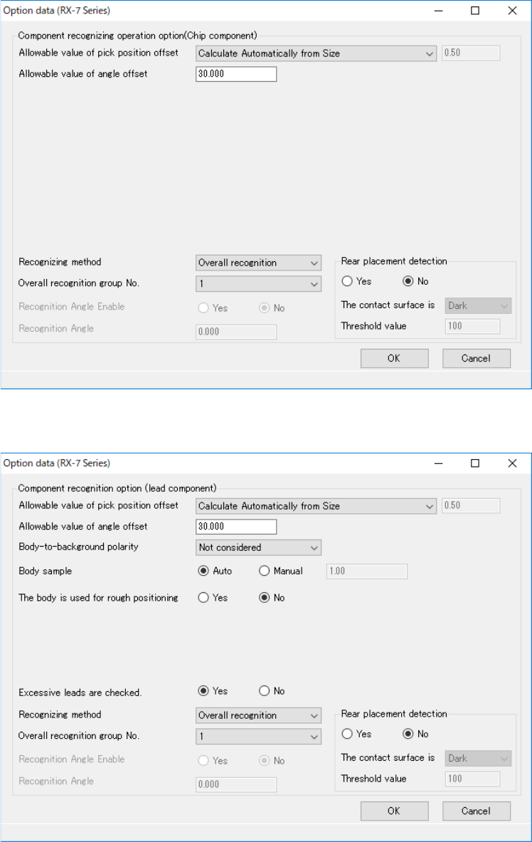
Option
When you press the <RX-7 series Option> button, the “Option data” screen appears.
The items displayed on this screen vary depending on the component shape type to be used with
the RX-7 series.
This is indicated when the form
type is “Chip component.”
JaNets Instruction Manual 7. Program Editor
7-83
◆ Chip component
Figure 7.4-127 RX-7 Series Option data screen (Chip component)
◆ Lead component
Figure 7.4-128 RX-7 Series Option data screen (Lead component)