JANETS_INM.pdf - 第293页
JaNets In structio n Manual 7. Program Editor 7- 86 The setting ite ms dis played on t his “ Opti on data ( RX - 7 series )” scr een vary dependin g on the component s hape ty pe to be use d with the RX -7 ser ies as sho…

JaNets Instruction Manual 7. Program Editor
7-85
Set the following items on the “Option data (RX-7 series)” screen.
Table 7.4-63 Option data screen (RX-7 Series) items
Item
Description
Allowable value of pick position
offset
Specify which range you select when a component is recognized.
When you select "Full screen," a component is recognized to the full
screen.
When you select "Specified Position," a component is recognized in the
specified area. When you select “Specified Position,” enter the recogni-
tion area.
When you select "Calculate Automatically from Part Size," a component
is recognized by setting up a recognition area automatically in consid-
eration of an angle and the angle gap permission.
The input range of the recognition area is from 0.00 to 1000.00.
The initial value is 0.50.
Allowable value of angle offset
Enter the allowable angle offset to be specified if the angle of a com-
ponent obtained by recognition does not match the assumed angle of
the component.
The input range is from 0.000 to 180.000. The initial value is 15.000.
Body-to-Background polarity
Select the difference of the light and darkness of the body and back-
ground of parts from among "Bright", "Dark," and "Not consider."
“Not considered” is selected as the initial setting.
Ball polarity
Select “The body is dark” or “The body is bright” as the difference of
brightness between the body and the ball. “The body is dark” is selected
as the initial setting.
Body Sub Sample
Specify the sample coefficient used at the time of body detection.
When you calculate a suitable body sub sample automatically, check
the check box of “Auto”.
Select “Manual” to set a coefficient.
The input range of the coefficient is from 1.00 to 24.00.
The initial value is 1.00.
Apparent ball size ratio
Enter the ratio of the “recognized ball size” to the “actual ball size” if the
recognized ball size is different from the actual ball size.
The input range is from 0.01 to 200.00. The initial value is 100.00.
Use Body for Rough
Positioning
When the system calculates the rough position of a component, it uses
the body information to obtain the rough position. “No” is selected
initially.
Check the Excessive Lead
Check a check box if you set recognition to NG to detect an excessive
lead when there are more leads of actual parts than the number of leads
on data.
“Ye s ” is selected initially.
Recognizing
Select the component recognition method of a general-purpose head,
“Overall recognition” or “Individual recognition.”
“Overall recognition” is selected initially.
Overall recognition group No.
Select a group number that allows a general-purpose head to recognize
components at the same time under the same level of lighting when
“Overall recognition” is selected. The initial value is 1.
Rear placement detection
Set whether to detect existence of a component already placed on the
rear of a board when a component is picked up.
“No” is selected initially.
Rear placement detection
The contact surface
Select the brightness of the contact surface, “Dark” or “Bright.”
“Dark” is selected as the initial setting.
Rear placement detection
threshold value
Enter a threshold value of the luminance for deciding the brightness of
the contact surface.
The input range is from 0 to 255. The initial value is 100.

JaNets Instruction Manual 7. Program Editor
7-86
The setting items displayed on this “Option data (RX-7 series)” screen vary depending on the
component shape type to be used with the RX-7 series as shown below.
Table 7.4-64 Component shape type requirements for the setting items
displayed on the “Option data (RX-7 Series)” screen
Item
Chip
component
Lead
component
BGA
component
Odd-shape
body (with-
out lead)
Odd-shape
body (with
lead)
Odd-shape
body (with
bowl)
Allowable value of pick
position offset
○ ○ ○ ○ ○ ○
Allowable value of
angle offset
○ ○ ○ ○ ○ ○
Body-to-Background
polarity
- ○ ○ ○ ○ ○
Ball polarity - - ○ - ○
Body Sub Sample - ○ ○ ○ ○ ○
Apparent ball size
ratio
- - ○ - ○
Use Body for Rough
Positioning
- ○ ○ - ○ ○
Check the Excessive
Lead
- ○ - ○ ○
Recognizing ○ ○ ○ ○ ○ ○
Overall recognition
group No.
○ ○ ○ ○ ○ ○
Rear placement
detection
○ ○ - -
JaNets Instruction Manual 7. Program Editor
7-87
Chip component
The <Edit> button is disabled.
You do not have to set any vision data for an RX-7 series.
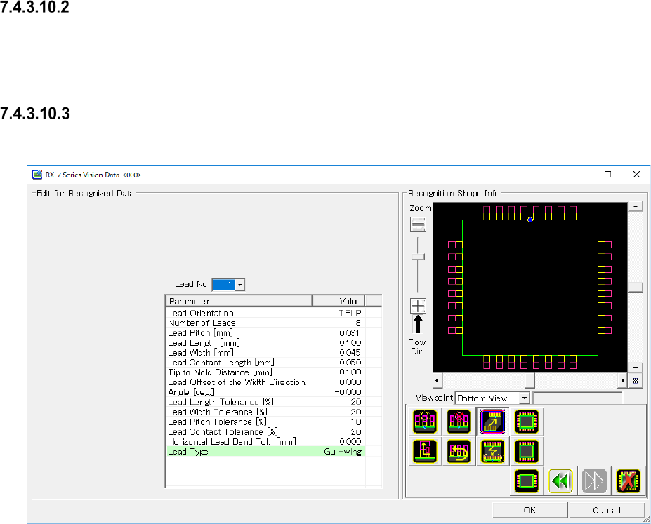
Lead component
When you press the <Edit> button, the screen like one shown below appears.
Figure 7.4-130 “RX-7 Series Vision Data <SOP>” screen (lead component)