JANETS_INM.pdf - 第294页
JaNets In structio n Manual 7. Program Editor 7- 87 C hip component The <Edit> but ton is di sabled. Y ou do not have to set any vision data for a n RX - 7 series . Lead component When you pres s the <Ed it> …

JaNets Instruction Manual 7. Program Editor
7-86
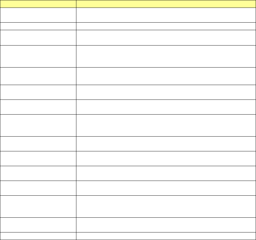
The setting items displayed on this “Option data (RX-7 series)” screen vary depending on the
component shape type to be used with the RX-7 series as shown below.
Table 7.4-64 Component shape type requirements for the setting items
displayed on the “Option data (RX-7 Series)” screen
Item
Chip
component
Lead
component
BGA
component
Odd-shape
body (with-
out lead)
Odd-shape
body (with
lead)
Odd-shape
body (with
bowl)
Allowable value of pick
position offset
○ ○ ○ ○ ○ ○
Allowable value of
angle offset
○ ○ ○ ○ ○ ○
Body-to-Background
polarity
- ○ ○ ○ ○ ○
Ball polarity - - ○ - ○
Body Sub Sample - ○ ○ ○ ○ ○
Apparent ball size
ratio
- - ○ - ○
Use Body for Rough
Positioning
- ○ ○ - ○ ○
Check the Excessive
Lead
- ○ - ○ ○
Recognizing ○ ○ ○ ○ ○ ○
Overall recognition
group No.
○ ○ ○ ○ ○ ○
Rear placement
detection
○ ○ - -
JaNets Instruction Manual 7. Program Editor
7-87
Chip component
The <Edit> button is disabled.
You do not have to set any vision data for an RX-7 series.
Lead component
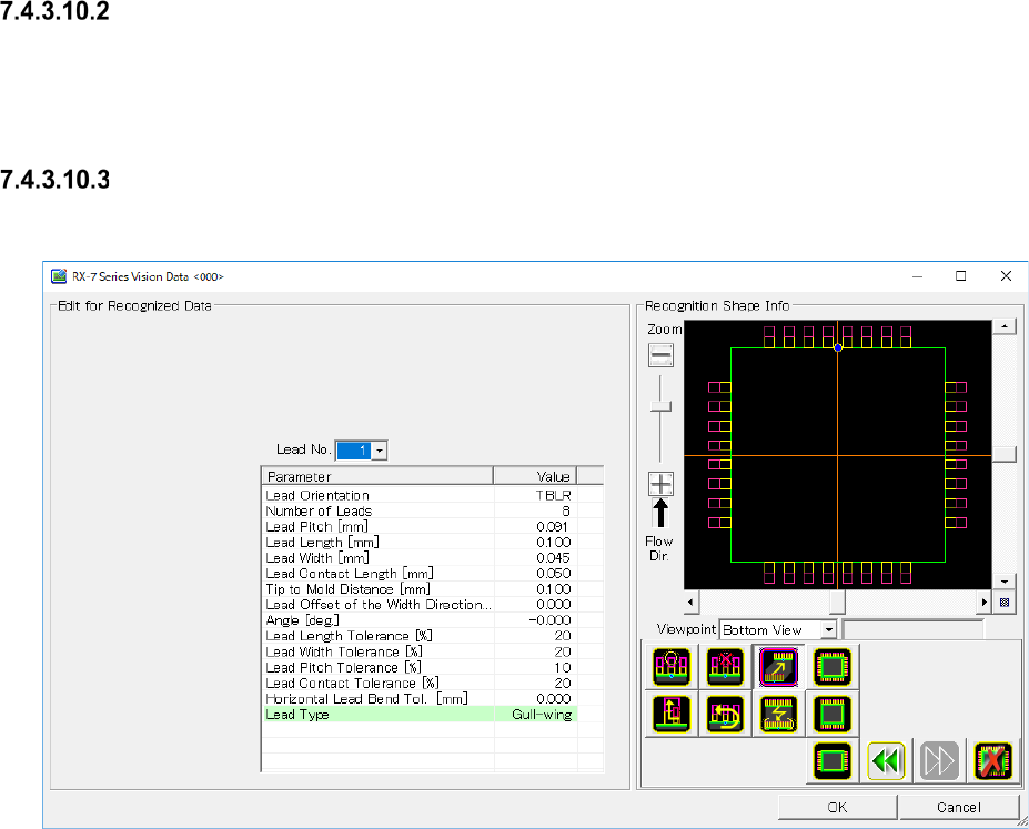
When you press the <Edit> button, the screen like one shown below appears.
Figure 7.4-130 “RX-7 Series Vision Data <SOP>” screen (lead component)
JaNets Instruction Manual 7. Program Editor
7-88
Set the following items on the “RX-7 series Vision Data” screen for a lead component.
Table 7.4-65 RX-7 Series Vision Data screen (lead component) setting items
Item name
Description
Lead No.
The setting of the parameter is enabled by a group unit.
By the following, the one group unit is set.
Lead Orientation
Set the lead existing direction
Number of Leads
Enter the number of leads
Input range of 1 to 999. (Default: 8 )
Lead Pitch Enter the distance between two consecutive leads (distance of the
center of one lead and that of the next lead)
Input range of 0.001 to 99.999. (Default: 0.000.)
Lead Length
Enter the lead length.
Input range of 0.001 to 99.999. (Default: 0.000.)
Lead Width
Enter the lead width.
Input range of 0.001 to 99.999. (Default: 0.000.)
Lead Contact Length
Enter the distance between a lead and the contact surface of a board.
Input range of 0.001 to 99.999. (Default: 0.000.)
Tip to Mold Distance
Enter the distance between the tip of a lead and the mold section.
Input range of -999.999 to 999.999. (Default: It varies according to mold
dimensions)
Lead Offset of the Width
Direction
Enter offset of the lead center viewed from the center of a component.
Input range of -999.999 to 999.999. (Default: 0.000.)
Lead Length Tolerance
Enter the allowable ratio of the lead length to be recognized.
Input range of 1 to 99. (Default: 20.)
Lead Width Tolerance
Enter the allowable ratio of the lead length to be recognized.
Input range of 1 to 99. (Default: 20.)
Lead Pitch Tolerance
Enter the allowable ratio of the lead pitch to be recognized.
Input range of 1 to 99. (Default: 10.)
Contact Length Tolerance
Enter the allowable ratio of the lead contact surface length to be recog-
nized.
Input range of 1 to 99. (Default: 20.)
Horizontal Lead Bend Tol.
Enter the allowable bentness value of the tip of a lead as the length.
Input range of 0.000 to 99.999. (Default: 0.000)
Lead Type
Select a lead type from between "Gull-wing" and "J-lead."