JANETS_INM.pdf - 第295页
JaNets In structio n Manual 7. Program Editor 7- 88 S et the follow ing item s on the “ RX - 7 ser ies V ision Data ” screen for a lead co mponent . T able 7.4 - 65 RX - 7 S er ies V ision D ata screen (lead component) s…
JaNets Instruction Manual 7. Program Editor
7-87
Chip component
The <Edit> button is disabled.
You do not have to set any vision data for an RX-7 series.
Lead component
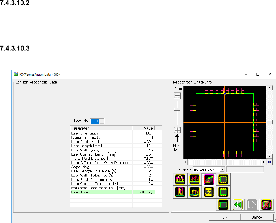
When you press the <Edit> button, the screen like one shown below appears.
Figure 7.4-130 “RX-7 Series Vision Data <SOP>” screen (lead component)
JaNets Instruction Manual 7. Program Editor
7-88
Set the following items on the “RX-7 series Vision Data” screen for a lead component.
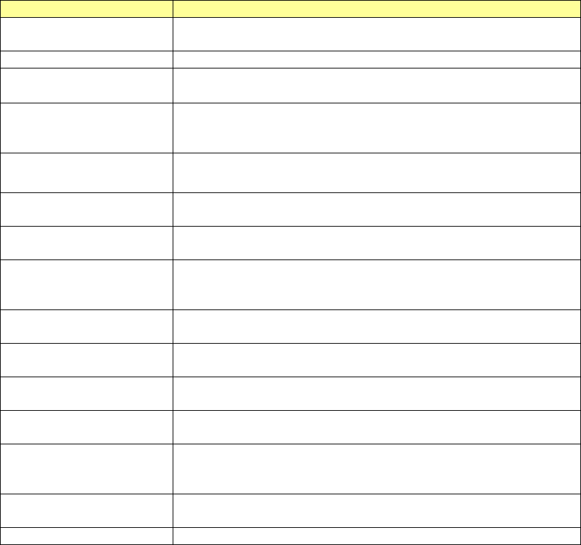
Table 7.4-65 RX-7 Series Vision Data screen (lead component) setting items
Item name
Description
Lead No.
The setting of the parameter is enabled by a group unit.
By the following, the one group unit is set.
Lead Orientation
Set the lead existing direction
Number of Leads
Enter the number of leads
Input range of 1 to 999. (Default: 8 )
Lead Pitch Enter the distance between two consecutive leads (distance of the
center of one lead and that of the next lead)
Input range of 0.001 to 99.999. (Default: 0.000.)
Lead Length
Enter the lead length.
Input range of 0.001 to 99.999. (Default: 0.000.)
Lead Width
Enter the lead width.
Input range of 0.001 to 99.999. (Default: 0.000.)
Lead Contact Length
Enter the distance between a lead and the contact surface of a board.
Input range of 0.001 to 99.999. (Default: 0.000.)
Tip to Mold Distance
Enter the distance between the tip of a lead and the mold section.
Input range of -999.999 to 999.999. (Default: It varies according to mold
dimensions)
Lead Offset of the Width
Direction
Enter offset of the lead center viewed from the center of a component.
Input range of -999.999 to 999.999. (Default: 0.000.)
Lead Length Tolerance
Enter the allowable ratio of the lead length to be recognized.
Input range of 1 to 99. (Default: 20.)
Lead Width Tolerance
Enter the allowable ratio of the lead length to be recognized.
Input range of 1 to 99. (Default: 20.)
Lead Pitch Tolerance
Enter the allowable ratio of the lead pitch to be recognized.
Input range of 1 to 99. (Default: 10.)
Contact Length Tolerance
Enter the allowable ratio of the lead contact surface length to be recog-
nized.
Input range of 1 to 99. (Default: 20.)
Horizontal Lead Bend Tol.
Enter the allowable bentness value of the tip of a lead as the length.
Input range of 0.000 to 99.999. (Default: 0.000)
Lead Type
Select a lead type from between "Gull-wing" and "J-lead."
JaNets Instruction Manual 7. Program Editor
7-89
BGA information
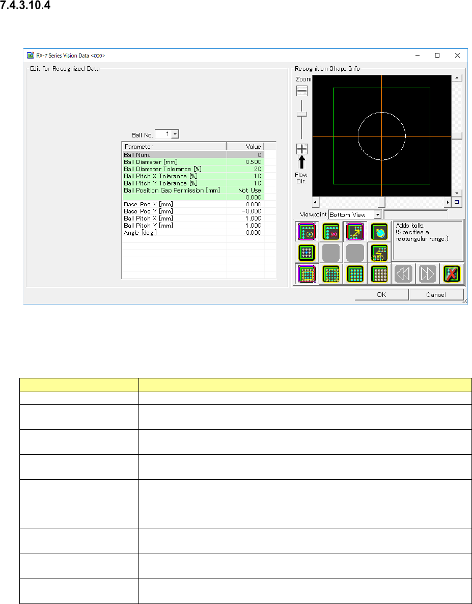
When you press the <Edit> button, the screen like one shown below appears.
Figure 7.4-131 “RX-7 Series Vision Data <BGA> screen (BGA component)
Set the following items on the “RX-7 series Vision Data” screen for a BGA component.
Table 7.4-66 RX-7 Series Vision Data screen (BGA component) setting items
Item name
Description
Ball Num
It cant be input. The number of balls arranged by a tool button is indicated.
Ball Diameter Enter the balls diameter.
Input range of 0.001 to 99.999. (Default: 0.500)
Ball Diameter Tolerance
Enter the allowable ratio of the ball diameter.
Input range of 1 to 99. (Default: 20)
Ball Pitch X/Y Tolerance Enter the allowable ratio of the ball pitch in the X direction and that in the Y
direction respectively. Input the range of 1 to 99. (Default: 10)
Ball Position Gap Permis-
sion
The location difference tolerance which is at the time of ball recognition is es-
tablished. Defaults" Not used".
Setting when you select the "use" will can be input
Input range of 0.001 to 99.999.
Base Pos X/Y The standard position of the ball group is input.
Input the range of -99.999 to 99.999. (Default: 0.000)
Ball Pitch X/Y
Pitch of the ball of the x-direction and y-direction is input.
Input the range of -0.001 to 99.999. (Default: 1.000)
Angle Inclination of the ball is input.
Input the range of -360.00 to 360.000. (Default: 0.000)