JANETS_INM.pdf - 第306页
JaNets In structio n Manual 7. Program Editor 7- 99 Clinch Pattern Setting Clinch Patter n Settin g Screen is t he scree n to set pair in format ion for ever y clinch pat tern. There are C linch Patt ern Settin g Screens…
JaNets Instruction Manual 7. Program Editor
7-98
Clinch
Clinch Screen is the screen to set Clinch Information against component data.
Clinch Screen becomes valid when JM-100 is existed on the line and [Other Component], [Inser-
tion Component] and [Electrolytic Capacitor] are selected.
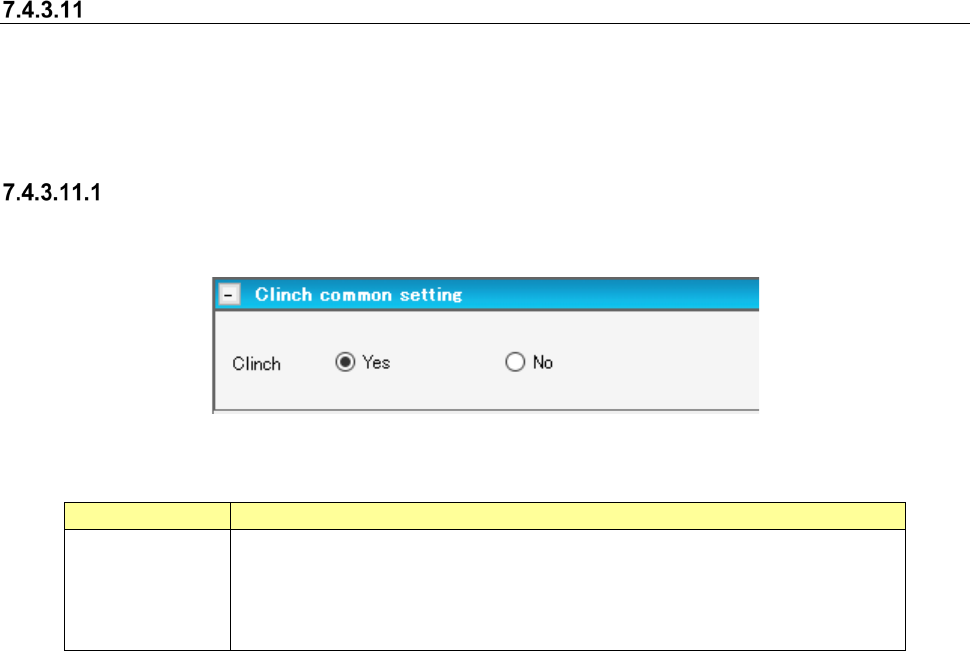
Clinch Common Setting
Clinch Common Setting Screen is the screen to set the clinch execution information at clinch.
Figure 7.4-135 Clinch Common Setting Screen
Table 7.4-68 Clinch Common Setting Items
Item name
Description
Clinch
Select whether to use clinch or not by the radio button.
The default value differs depending on component category.
The default when the component category is inserted component, INS electrolytic
capacitor and other components shall be [Yes].
The default for other component categories shall be [No].
JaNets Instruction Manual 7. Program Editor
7-99
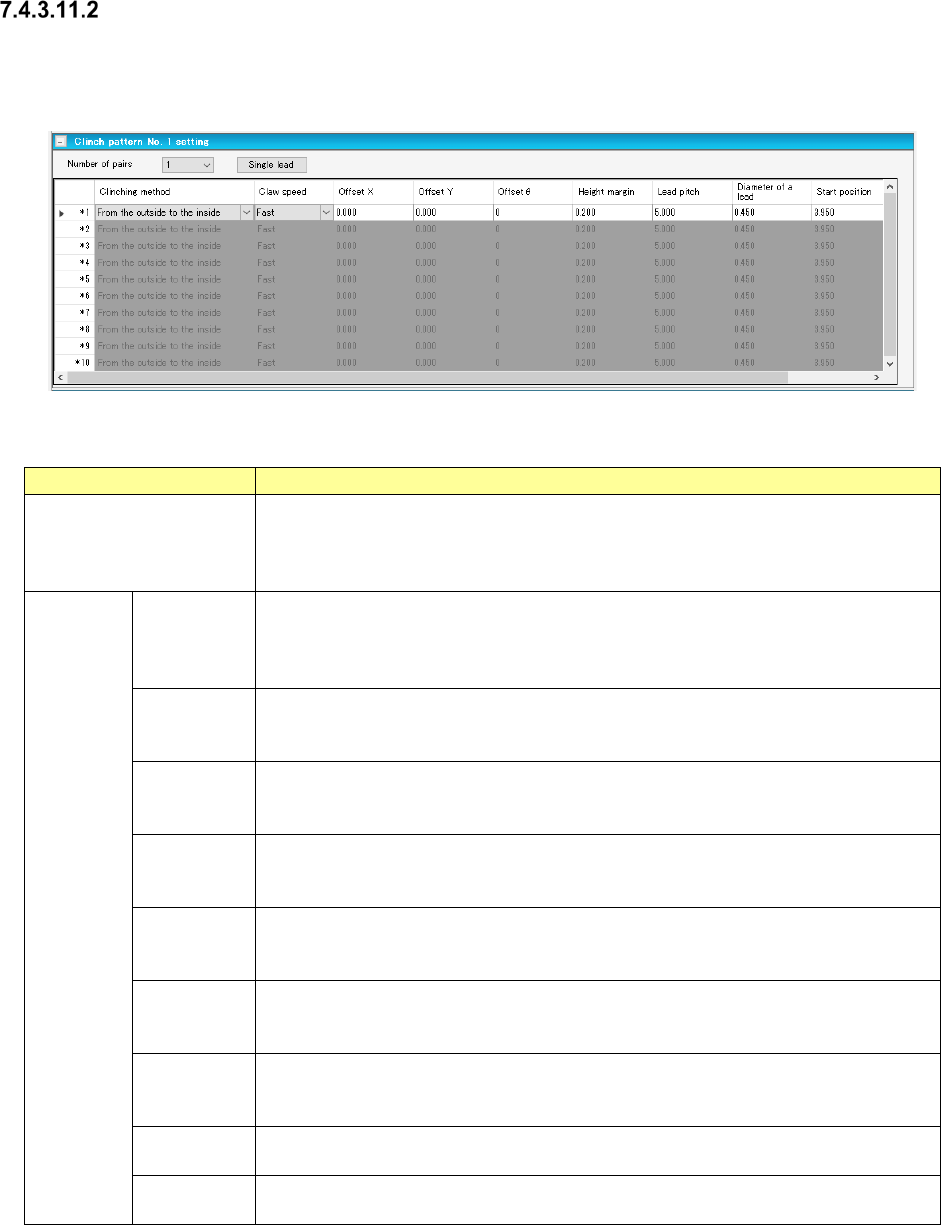
Clinch Pattern Setting
Clinch Pattern Setting Screen is the screen to set pair information for every clinch pattern.
There are Clinch Pattern Setting Screens, No. 1 through No. 4.
Figure 7.4-136 Clinch Pattern Setting Screen
Table 7.4-69 Clinch Pattern Setting Items
Item name
Description
Number of Pairs
Select the number of pairs used in pattern setting by the combo box.
Input Range: 1 ~ 10
Default Value: 1
The contents of pair information only for numbers assigned by the number of pairs.
Pair
Setting
Clinch
Method
Select Clinch Method by the combo box.
The default value is “from outside toward inside”.
Select from “from outside toward inside”, “from inside toward outside”, “CW” and
“CCW”.
Claw Speed
Select claw acceleration by the combo box.
The default value is “High Speed”.
Select from “High Speed”, “Med Speed” and “Low Speed”.
Offset X/Y
Enter the Offset X and Y of mounting point reference.
Input Range: -85.000 ~ 85.000mm
Default Value: 0.000mm
Offset Theta
Enter the angle offset of mounting point reference.
Input Range: 0 ~ 179
Default Value: 0
Height
Margin
Enter the margin after clinch.
Input Range: 0.000 ~ 10.000mm
Default Value: Depends on clinch method
Lead Pitch
Enter the lead pitch.
Input Range: 5.000 ~ 20.000mm
Default Value: 5.000mm
Lead
Diameter
Enter the lead diameter.
Input Range: 0.450 ~ 1.000mm
Default Value: 0.450mm
Starting
Position
Enter the starting position.
The default value and input range differ depending on the clinch method.
Moving
Amount
Enter the moving amount.
The default value and input range differ depending on the clinch method.
JaNets Instruction Manual 7. Program Editor
7-100
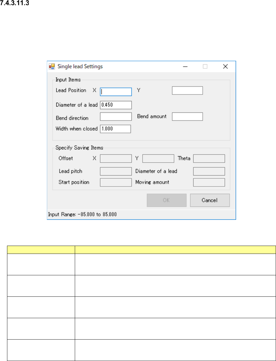
Single Lead Setting
Single Lead Setting Screen is the screen to support the pair information entry at single lead.
Entry becomes capable when the selected pair clinch method is “from outside toward inside” or
“from inside toward outside”.
The contents of output item are reflected to the selected pair when all input items were set and
pressing OK button.
Figure 7.4-137 Single Lead Setting Screen
Table 7.4-70 Single Lead Setting Items
Item name
Description
Lead Position, X/Y
Enter the lead positions, X and Y, at mounting point reference.
Input Range: -85.000 ~ 85.000mm
Default Value: Blank
Lead Diameter
Enter the lead diameter.
Input Range: 0.450 ~ 1.000mm
Default Value: Pair lead diameter selected
Bending Direction
Enter the bending direction
Input Range: 0 ~ 359
Default Value: Blank
Bending Amount
Enter the bending amount
Input Range: 2.500 ~ 10.000mm
Default Value: Blank
Width at Closing
Enter the width at closing.
Input Range: 1.000 ~ 5.000mm
Default Value: 1.000mm