JANETS_INM.pdf - 第308页
JaNets In structio n Manual 7. Program Editor 7- 101 7.4.4 Editing adhesive data “ Adhesive Pattern ” screen This scree n allows y ou to set the adhe sive in formati on to be use d for the corr esponding c ompo- nent. Wh…
JaNets Instruction Manual 7. Program Editor
7-100
Single Lead Setting
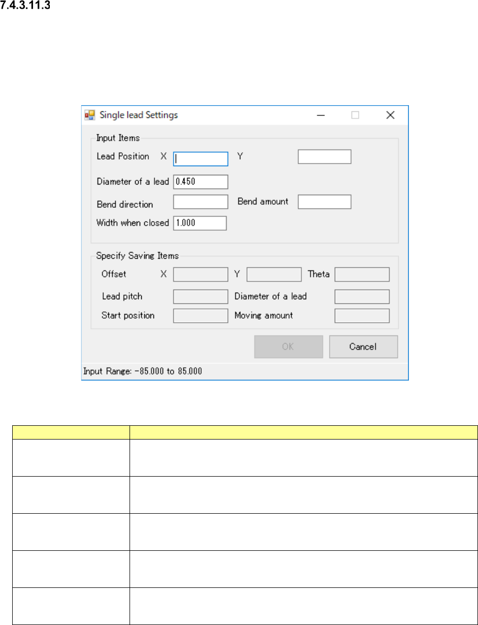
Single Lead Setting Screen is the screen to support the pair information entry at single lead.
Entry becomes capable when the selected pair clinch method is “from outside toward inside” or
“from inside toward outside”.
The contents of output item are reflected to the selected pair when all input items were set and
pressing OK button.
Figure 7.4-137 Single Lead Setting Screen
Table 7.4-70 Single Lead Setting Items
Item name
Description
Lead Position, X/Y
Enter the lead positions, X and Y, at mounting point reference.
Input Range: -85.000 ~ 85.000mm
Default Value: Blank
Lead Diameter
Enter the lead diameter.
Input Range: 0.450 ~ 1.000mm
Default Value: Pair lead diameter selected
Bending Direction
Enter the bending direction
Input Range: 0 ~ 359
Default Value: Blank
Bending Amount
Enter the bending amount
Input Range: 2.500 ~ 10.000mm
Default Value: Blank
Width at Closing
Enter the width at closing.
Input Range: 1.000 ~ 5.000mm
Default Value: 1.000mm
JaNets Instruction Manual 7. Program Editor
7-101
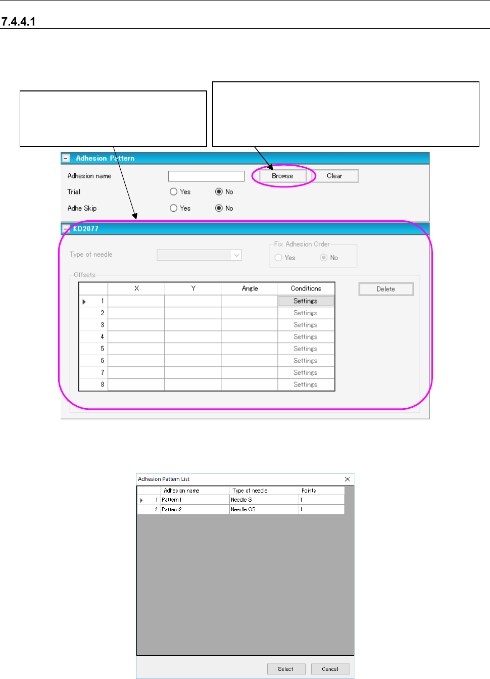
7.4.4 Editing adhesive data
“Adhesive Pattern” screen
This screen allows you to set the adhesive information to be used for the corresponding compo-
nent. When you select “Component Data” from the tree view, and then the “Dispensing,” this
screen appears.
Figure 7.4-138 “Adhesive Pattern” screen
When you select the <Browse> button on the screen above, the “Adhesive Pattern List” appears
as shown below.
Figure 7.4-139 “Adhesive Pattern List”
This button displays the “Adhesive Pattern List,” which shows
the adhesive data created on the “Adhesive Data” screen. You
can select an adhesive pattern to be used to dispense adhe-
sive on the “Adhesive Pattern List.” When you select a pattern,
its name is displayed on the screen.
When you enter the “Adhesion name”
field, you can edit data displayed in this
area. See Section “
7.4.4.2
Adhesive data” for how to enter data.
JaNets Instruction Manual 7. Program Editor
7-102
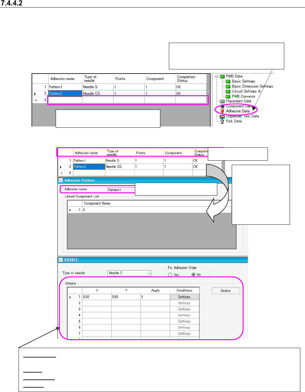
Adhesive data
When an adhesive dispenser is used in the selected production line, enter information on adhesive
points on the “Adhesive Data” screen.
* If there is not any adhesive dispenser in the selected production line, you do not have to make
any setting on this screen.
Figure 7.4-140 “Adhesive Data” screen
Figure 7.4-141 Adhesive data form screen
Adhesive data list
When you dou-
ble-click the de-
sired line on the
“Adhesive data list”
above, the “Adhe-
sive data form”
screen appears.
Offset (X,Y): Specify an offset from the component placement coordinates to the adhesive point if the angle
of the component is 0 degrees when it is placed on a board.
Angle: Specify the angle of a needle against the angle of a component when adhesive is dispensed.
Conditions: When you select the <Settings> button, the “Dispensing Condition” screen appears.
Delete: Deletes the offset data on the specified adhesive dispensing point.
When you create new adhesive data,
enter data in a blank cell of the grid.
When you select “Adhesive Data” from the
tree view, the following Adhesive data list
appears on the screen.
Display only: You cannot edit it.