JANETS_INM.pdf - 第314页
JaNets In structio n Manual 7. Program Editor 7- 107 7.4.6 Editing pick data The “ Pic k Data ” scr een allow s you to set a feeder att achment po sition an d so on. Figure 7.4 - 148 Pick d ata form sc reen Figure 7.4 - …
JaNets Instruction Manual 7. Program Editor
7-106
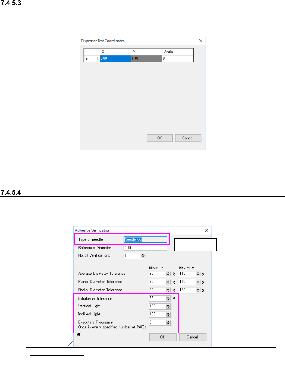
“Dispenser Test Data (Dispenser Test Coordinates)” screen
This screen allows you to edit the coordinates of each adhesive dispensing point used for testing.
When you select the <Edit> button on the “Dispenser Test Data” screen, the “Dispense Test Co-
ordinates” screen appears.
Figure 7.4-146 “Dispenser Test Coordinates” screen
* The default values are calculated and displayed based on the settings in the “Front Pos.,” “No. of
Times,” “Direction” and “Pitch between Components” fields.
Dispenser Test Data (Adhesive Verification)
Set the inspection conditions for verifying dispenser test data on the following screen. When you
select the <Inspection> button on the “Dispenser Test Data” screen, the “Adhesive Verification”
screen appears.
Figure 7.4-147 “Adhesive Verification” screen
Display only
Imbalance Tolerance: To check adhesive dispensing with a needle for two points or four points, set the
tolerance of the ratio of the minimum diameter of points at which adhesive is dispensed at a time to
the maximum diameter.
Executing Frequency: Specify the frequency of the inspection to be executed: how many boards is the
inspection to be executed per.
JaNets Instruction Manual 7. Program Editor
7-107
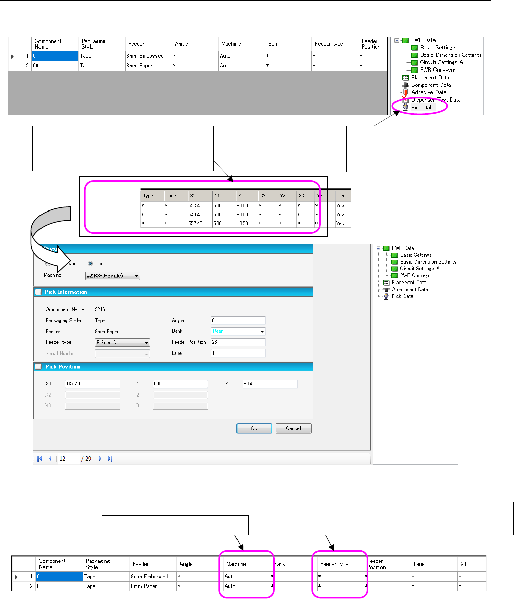
7.4.6 Editing pick data
The “Pick Data” screen allows you to set a feeder attachment position and so on.
Figure 7.4-148 Pick data form screen
Figure 7.4-149 Pick List
When you double-click a line of the pick
data list, the following “Pick data form”
screen appears.
When you select “Pick Data” from
the tree view, the “Pick data list”
appears on the screen.
Changes the feeder type.
[Mxxx]: Mechanical bank (Mechanical feeder)
Display only in the line mode
JaNets Instruction Manual 7. Program Editor
7-108
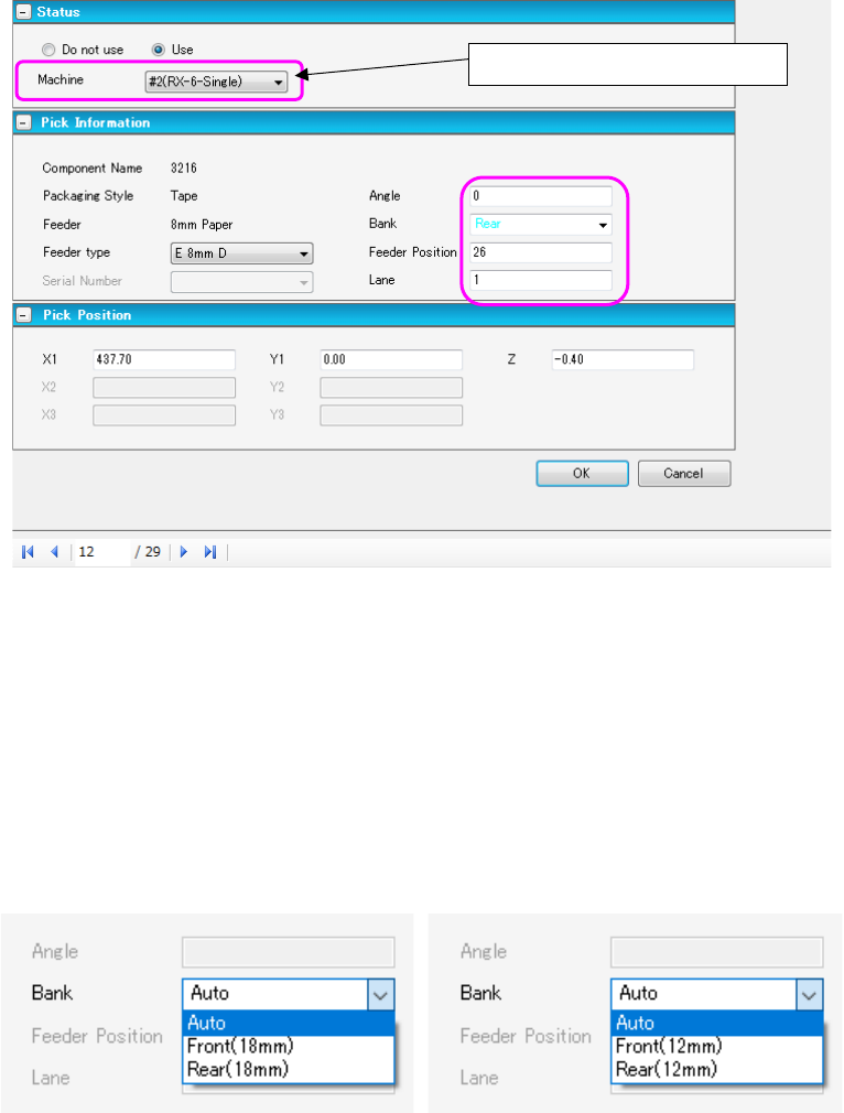
Figure 7.4-150 Pick Form
* In the EPU mode, “Machine specification” is not displayed.
* When you use an RX-7 series, numbers for indicating a position at which a component supply
device is to be mounted are different from those of other machine models.
Feeders are assigned to odd-numbered slots. However, when you use an 8-mm type D feeder
on the lane 2, it is assigned to an even-numbered slot.
* When you use a JM-100, the bank type is displayed after the side, front or rear.
Figure 7.4-151 Bank type display
Display only in the line mode