JANETS_INM.pdf - 第320页
JaNets In structio n Manual 7. Program Editor 7- 113 About the Boar d Viewer Figure 7.5 -3 “ Board View er ” screen Figure 7.5 -4 “ Board View er ” T oolbar (display of t he ima ge) You can chec k the P W B imag e obtain…
JaNets Instruction Manual 7. Program Editor
7-112
About the tabs displayed on the viewer display area
Guidance: Displays the description of the item selected at the present.
Coherence Check Results: Displays the results of the data coherence check.
Board Viewer: Allows you to check the board transport direction, board layout offset, positioning
hole position, component assignment and so on with showing the image of a board.
When you double-click the desired component, the system selects its Placement data and dis-
plays it on the screen.
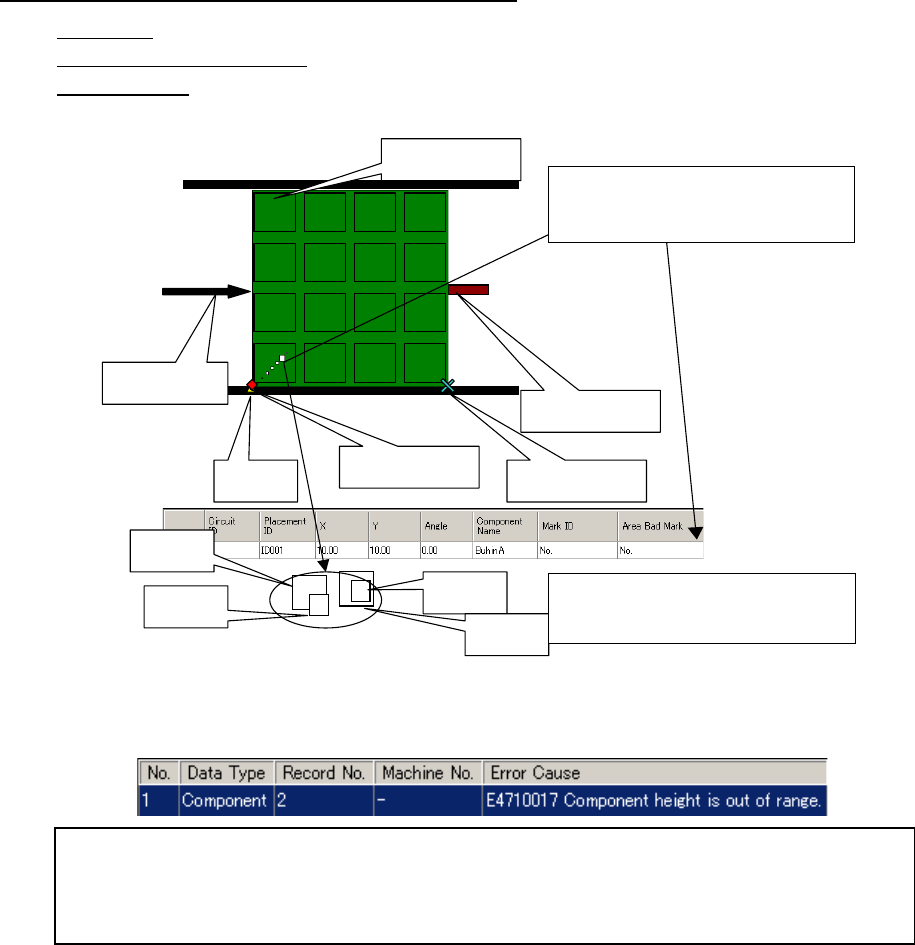
Figure 7.5-2 Description of each item displayed on the Board Viewer
Circuit assignment
Board transport
direction
Hole
position
Component
A
Component
B
Component
C
Component
D
The system draws a component whose size is
smaller than those of others over them so that
you can understand how components are over-
lapped.
PWB reference posi-
tion
Layout end point
Stopper pin
When you double-click the displayed com-
ponent, its Placement data is displayed.
When you double-click the desired line, the cursor moves to the “Height” cell of the outer di-
mensions of the corresponding Component data. The system also displays the data coher-
ence error message.
When you double-click the error message, the cursor moves to the item that caused the error.
JaNets Instruction Manual 7. Program Editor
7-113
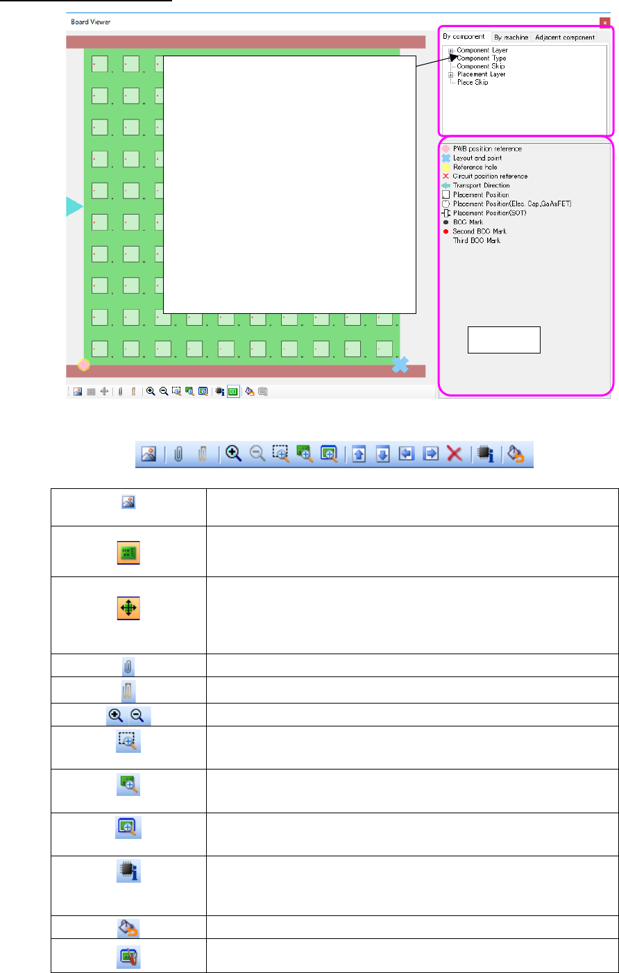
About the Board Viewer
Figure 7.5-3 “Board Viewer” screen
Figure 7.5-4 “Board Viewer” Toolbar
(display of the image)
You can check the PWB image obtained with a scanner with the
placement data.
Displays/hides a PWB image.
This button is enabled when you obtain a PWB image with the <Display
of the image> button above.
(Change of a PWB im-
age)
Changes the PWB image size, and/or moves/rotates a PWB image.
Displays the tool bar for changing a PWB image.
This button is enabled when you obtain a PWB image with the <display
of the image> button above.
Displays/hides the tree view.
Displays/hides the legends.
Enlargement/reduction
(Rectangular zoom)
Zooms the area specified with a mouse
(100% zoom)
Displays in the same size as a PWB size.
(Whole zoom)
Displays the whole PWB according to the size of the screen.
(ID information for
placement)
Displays in a pop-up window component ID, component name, com-
ment, component type, and component outside dimensions by clicking
component.
Returns the displayed color by machine to the default.
Adjusts a display size so that it may be displayed in the same size as the
outside dimension of board when it is displayed with 100% zoom.
Legends
The selected trees are distinguished in
colors.
Component:
it is distinguished in color by component.
Machine:
it is distinguished in color by machine to
be used.
(* optimized)
Adjacent components:
Two adjacent placed components are
displayed in the tree view in the follow-
ing order: Component type – Base
component – Adjacent component.
JaNets Instruction Manual 7. Program Editor
7-114
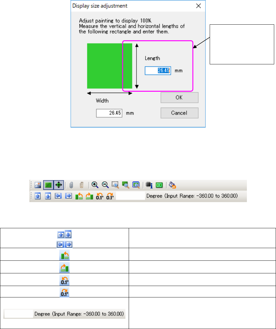
A board viewer is displayed with the same size as the set outside dimension of a board through
100 zoom.
However, depending on a display size and the graphic resolution of a display unit, it may be dis-
played with a different size from an outside dimension of a board. In this case, click the "display
size adjustment" button of a tool bar, and adjust a display size so that it may be displayed with an
actual outside dimension of a board.
(It is an effective button for a "100% zoom" display.)
Figure 7.5-5 Display size adjustment screen
When you select the <Change of the PWB image> button above, the various buttons for changing
a PWB image are displayed on the tool bar.
Figure 7.5-6 Tool bar displayed when you select the <Change of the PWB image> button
Moves an image up/down or to the right/left.
Rotates an image to the left by 90 degrees.
Rotates an image to the right by 90 degrees.
Rotates an image to the left by 0.1 degree.
Rotates an image to the right by 0.1 degree.
Allows you to enter the rotation angle of an image viewed
from a horizontal direction (0 degrees) of the image.
When you enter a positive angle, an image is rotated to the
left. When you enter a negative angle, it is rotated to the
right.
Measure the vertical
length of the rectan-
gle displayed on the
screen, and enter
the length.