JANETS_INM.pdf - 第358页
JaNets In structio n Manual 7. Program Editor 7- 151 (4) Pick Data 1) Pick Dis trib ut i on When a mach ine is spe cified in the “ Machi ne” cell o n the “Pick Data” screen, select whether t o assign dat a as specifie d …
JaNets Instruction Manual 7. Program Editor
7-150
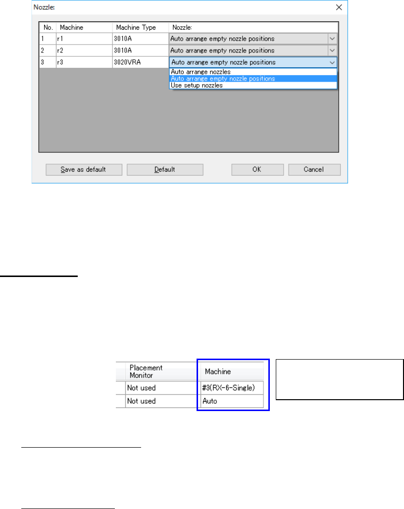
2) Individual Machine
When you select the “Individual Machine” radio button, the <Set> button is activated to
allow you to make settings depending on each machine.
Figure 7.7-4 Individual Machine
* When a “Manual nozzle attachment” “screw type nozzle” is selected on the “Option De-
vices” tab invoked with the [Machine] command of the Shopfloor Setup, only the “Use
setup nozzles” can be selected for the “Nozzle.”
(3) Placement Data
1) Placement Distribution
When a machine is specified in the “Machine” cell on the “Placement Data” screen, select
whether to assign component placement positions as specified or optimize them with
ignoring the specification.
This is an ineffective option when the number of machines is 1.
Figure 7.7-5 Placement Data
◆
Use manual assignments:
Assigns the specified component placement positions as specified, and assigns only the
component placement positions to which “Auto” is specified with the optimization func-
tion.
◆ Auto assign all data:
Ignores the specifications and optimizes all component placement positions.
2) Data Order
Specify the placement data order: input order (data entry order) or optimized order.
◆ Assign in input order of production file:
Placement data will be displayed in entry order (that is, not changed at all).
◆ Assign in optimized order:
Placement data will be displayed in the optimization order.
This order cannot be selected when an RX-7 series is on a line.
Select whether to disable or ena-
ble the specification in the “Ma-
chine” cell.
JaNets Instruction Manual 7. Program Editor
7-151
(4) Pick Data
1) Pick Distribution
When a machine is specified in the “Machine” cell on the “Pick Data” screen, select
whether to assign data as specified or ignore the specification.
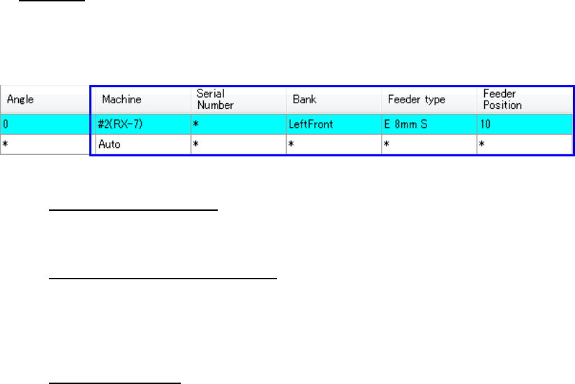
Figure 7.7-6 Pick data
◆
Use manual assignments:
Assigns the specified feeders based on your specifications, and optimizes only feeders to
which “Auto” is specified.
◆ Use manual machine assignments:
Ignores the specified “Bank” setting, and enables only the specified “Machine” setting. In
the example above, although “the feeder position ‘10’ of the second RX-7” is specified,
the “Left Front 10” is ignored and only the setting of “#2(RX-7)” is effective in this case.
The case where the number of machines is 1 is the same as “All is distributed”.
◆ Auto assign all data:
Ignores the specified feeder assignments and optimizes all assignments.
2) Assign several components to each stick feeder
Normally, components used in an old type of stick feeders (that supply one stick feeder
with two or more sticks) are assigned to one feeder for one component type. If you
check this check box when there are stick components whose component types are the
same, they can be assigned to one feeder.
JaNets Instruction Manual 7. Program Editor
7-152
Feed back option
This option allows you to specify whether to perform the feedback process with the “tact simula-
tion,” and set the options for this feed back process. When you select the “Feed Back” option in the
option selecting area, the following “Feed Back” option screen appears in the option setting area.
* Feedback processing: Performs optimization in consideration of the feeder arrangement be-
tween machines in the decided feedback conditions repeatedly, and outputs the best result in the
feedback.
* A tact time does not change because a feeder is not exchanged between machines when the
conditions of optimization are to fix the feeder and to specify a station since the feedback pro-
cessing considers line balance.
* When “Tray” is selected as the “Packaging Style,” the tact simulation uses the coordinates of the
center point of the component supply device to perform the feedback processing. Therefore,
the actual time of each PWB may be different from the simulation result.
* When the number of component placement positions is small, the error rate becomes higher.
Therefore, when a small number of components are placed on a board, the actual time may be
different from the simulation result.
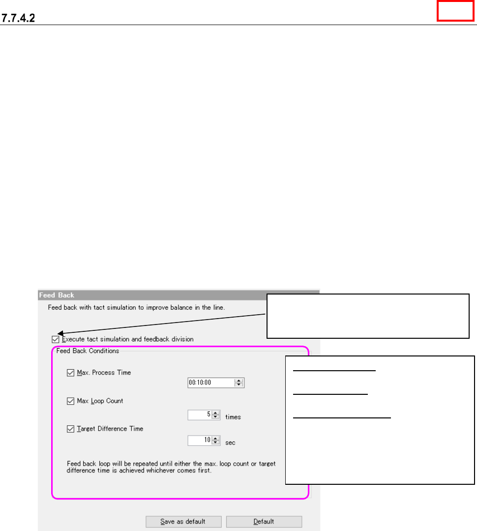
Figure 7.7-7 Feed back option
When you check this check box, the Optimize
application uses the tact simulator to execute
the feedback process.
Max. Process Time: Enter the time in the
format: hour:minute:second.
Max. Loop Count: Enter the number of
loops from 0 to 100.
Target Difference Time: Enter the time
from 0 to 60 seconds.
* When you check two or more check
boxes, the feedback process is stopped
if any of the conditions indicated with
these check boxes is satisfied.
Line