JANETS_INM.pdf - 第364页
JaNets In structio n Manual 7. Program Editor 7- 157 Priority of layers The placement order prior ity is decided acc ording t o the settings of the c heck boxes “ Cons ider t he component t ypes and h eights , ” “ Order …
JaNets Instruction Manual 7. Program Editor
7-156
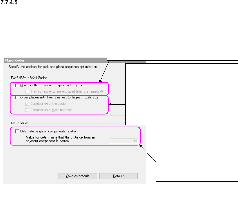
Placement Order option
This option allows you to specify the component pick-up and placement order. When you select
the “Place Order” option in the option selecting area, the following screen appears in the “optimize
option setting area”.
Figure 7.7-11 Place Order option
The machine types that can use the options
“Consider the component type and height” and “Place components for a small-diameter nozzle
first” are effective options for others than RX-7 series.
To RX-7 series, “Consider the component type and height” and “Place components for a
small-diameter nozzle first” are not applicable.
“Consider adjacent components” is an effective option only for RX-7 series. For others than RX-7
series, “Consider adjacent components” is not applicable.
For a line in which RX-7 series is positioned on the down-stream side and others than RX-7 series
are positioned on the upper-stream side, any placement order option cannot be specified.
When you check the “Order placements from smallest
to largest nozzle size” check box, the following set-
tings are enabled:
Consider on a line basis: Specify whether to con-
sider use of a small nozzle when the Optimize
application assigns component placement points
to machines.
Consider on a machine basis: Specify whether to
consider use of a small nozzle when the Optimize
application is performed for each machine.
"Calculate neighbor parts relation" --
When this option is enabled, the group
of components that are narrowly
neighbor is kept all together to place
components sequentially from
low-profile one.
The component with a shielding case
enables this function. The value of
narrow neighbor judgment distance is
used for a narrow neighbor judgment.
When “consider the Component types and heights” is checked,
the following setting is made effective.
Component types and heights: In optimization division, it is
set whether the part
JaNets Instruction Manual 7. Program Editor
7-157
Priority of layers
The placement order priority is decided according to the settings of the check boxes “Consider the
component types and heights,” “Order placements from smallest to largest nozzle size” of the
“Place Order” options and ”Calculate neighbor parts relation”, the placement layer and the com-
ponent layer as shown below:
Placement layer > Component layer > Calculate neighbor parts relation (when the “Place Order”
option is used) > Component type/Component height (when the “Place Order” option is used) >
Use of a small nozzle(s) (when the “Place Order” option is used)
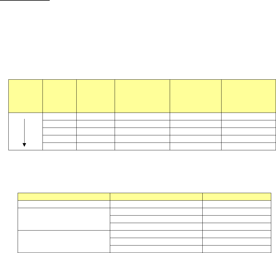
Example:
Placement
order
Placement
layer
Component
layer
Neighbor parts
[Component
height] (when the
“Place Order”
option is used)
Component
type/Component
height (when the
“Place Order”
option is used)
Use of a small
nozzle(s) (when
the “Place Order”
option is used)
1
1
0.5
1
501
3
4
0.5
3
503
4
4
1.0
4
502
6
3
1.5
1
504
7
7
3.0
7
508
The component types and heights are internally assigned to layers according to the following
specifications.
Table 7.7-3 Specifications of layer assignments for the component types/component heights
Component types
Component heights
Layer
Square chip resistor
0.0mm
<
H
≦
0.25mm
1
Component other than a square
chip resistor and an aluminum elec-
trolytic capacitor
0.0mm
<
H
≦
5.5mm
2
5.5mm
<
H
≦
12.0mm
3
12.0mm
<
H
4
Aluminum electrolytic capacitor
0.0mm
<
H
≦
5.5mm
5
5.5mm
<
H
≦
12.0mm
6
12.0mm
<
H
7
JaNets Instruction Manual 7. Program Editor
7-158
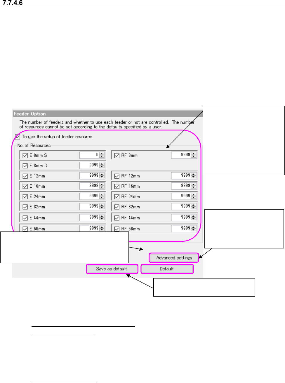
Feeder option
This option allows you to specify the feeder option when restricting the number of a feeder used
for every optimization.
When you select the “Feeder” option in the option selecting area, the following screen appears in
the option setting area.
You cannot specify a user default for this item.
The item of a feeder is enabled only when the electric (EF) bank is equipped with the production
line. You cannot select the item of a "Feeder" when not equipped.
If the electric (RF/EF) bank on the line has been fitted, to display the configuration control of the
RF feeder, but it does not do the view if they have not been fitted.
In the EPU mode, the data may be changed automatically according to the upper limit value
available in the target machine.
Figure 7.7-12 Feeder option
(1) To use the setup of feeder resource
◆Use in the line mode
Select whether to use this option. When using it, use the number of resources in the group
box under a checkbox. When not using it, use the value set on the “Equipment Setup” screen
of the Shopfloor Setup application. The "Not used" is a default in the setup of a feeder re-
source.
◆Use in the EPU mode
This option is enabled at all time and an option cannot be selected. Regarding the displayed
feeder, the equipment setting values set in the shop floor setup are ignored.
The setting of the number of resources
is not saved as the default value.
This is displayed only when the production line is
equipped with an electrical bank (RF).
You can set the use conditions of the attachment
and an “E 8mm D” feeder.
This setting is to be applied to
the feeder options other than
the number of resources.
(This is applied to the ad-
vanced settings also.
)
When you put a checkmark in
the check box “Use of the
feeder resource settings,” the
settings of the “Number of re-
sources” group are enabled.
When you uncheck the check
box for each feeder, the cor-
responding feeder is not used
as long as it is not a permanent
feeder.