JANETS_INM.pdf - 第372页
JaNets In structio n Manual 7. Program Editor 7- 165 FX -3 S eries options The follow ing screen is display ed by sel ecting the “ FX -3 S eries ” tab i n option s peculiar to the mod el. Figure 7.7 - 20 Options peculiar…
JaNets Instruction Manual 7. Program Editor
7-164
Machine Options option
This option allows you to set the optimize option for each machine type. When you select the
“Machine Options” option in the option setting area, the “Machine Type Specific” screen appears in
the option setting area.
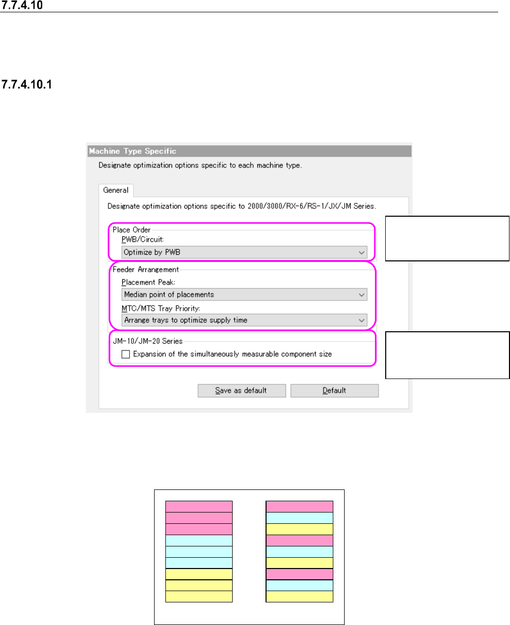
2000/3000/RX-6/RS-1/JX/JM Series options
When you select the “General” tab on the “Machine Type Specific” screen, the following screen
appears.
Figure 7.7-18 Machine Options – 2000/3000/RX-6/RS-1/JX/JM Series
The examples below show the assignments of component depending on your choice of the
“MTC/MTS Tray Priority.”
Component type A
A
A
Component type B
B
B
Component type C
C
C
Component type A
Component type B
Component type C
A
B
C
A
B
C
Group trays with same
component type together
Arrange trays to optimize
supply time
Figure 7.7-19 Example of components assignments vaying depending
on your choice of the “MTC/MTS Tray Priority” menu item.
You can set this menu
item forJM-10/JM-20 se-
ries machine only.
You can set this menu
item for a KE2000/JM-10
series machine only.
JaNets Instruction Manual 7. Program Editor
7-165
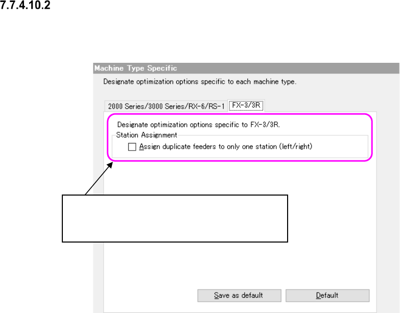
FX-3 Series options
The following screen is displayed by selecting the “FX-3 Series” tab in options peculiar to the
model.
Figure 7.7-20 Options peculiar to the model – FX-3 Series options
Division of station:
The following are choices for allocating the same
component to the left and right stations.
JaNets Instruction Manual 7. Program Editor
7-166
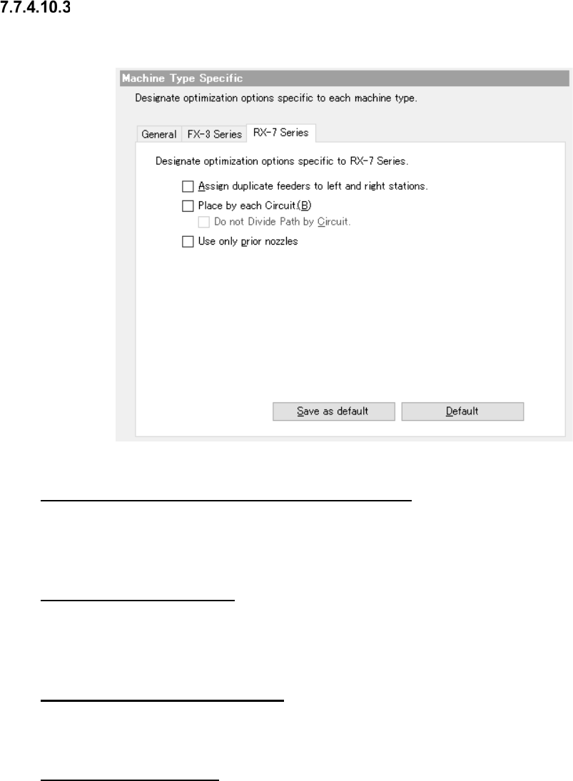
RX-7 Series options
When you select the “RX-7 Series” tab from Machine Type Specific, the following dialog box ap-
pears on the careen.
Figure 7.7-21 Machine Type Specific RX-7 Series option
“Assign duplicate feeders to left and right stations.”
When this option is enabled, the same components may be assigned to a station on either side in
order to maintain right-and-left balance. The same components are not assigned to a station on
either side when this option is disabled.
“Mounting for each circuit”
If this option is enabled, and when two or more circuits exist in a mount step, components are kept
from being assigned to two or more different circuits in one cycle. For the reference circuit only, the
placement order is determined.
“No path division for each circuit”
Set whether path division (placement point) is performed or not between stations for each circuit.
This is available when “Placement for each circuit” is enabled.
“Use only prior nozzles.”
For placing components for which multiple shared nozzles are set, check off this item for optimi-
zation. When the check box of this item is OFF (unchecked), the nozzle to be used is automatically
selected through optimization.