JANETS_INM.pdf - 第375页
JaNets In structio n Manual 7. Program Editor 7- 168 - Component infor mation (c omponent type, packagin g style, feeder t ype and feeding pitc h) of the Compon ent datab ase, that of the refer ence fe eder (or of a per …
JaNets Instruction Manual 7. Program Editor
7-167
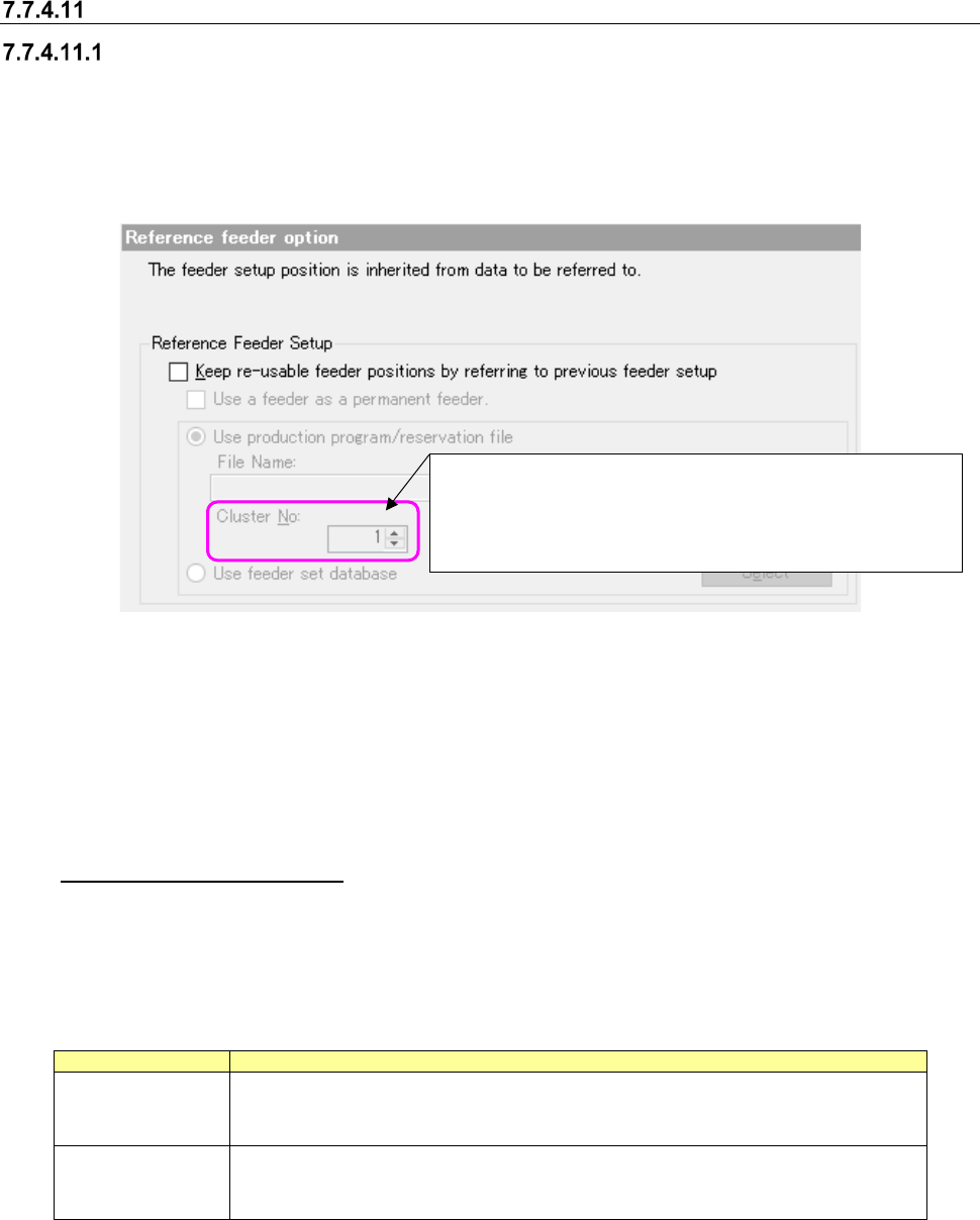
Reference feeder option
Reference Feeder Setup
The system refers to the feeder set information of other production programs or reservation files
and makes the feeder assignment of a production program contained in a reservation file that is to
be optimized common to the referred feeder set information.
* When a production line includes a JM series machine, the “Reference feeder option” cannot be
selected.
Figure 7.7-22 Reference Feeder Setup
When you select the <Browse> button, the system displays the dialog box for selecting a file. On
this dialog box, you can select a production program or a reservation file for the IS.
If you select a file whose line configuration is different from that of the active line set with the Job
Optimizer, the error message indicating that the selected file is different from that of the “Refer-
ence Feeder Setup” appears on the screen when you click the <Open> button on this dialog box.
Used as a permanent feeder
When you put a checkmark in this check box, the system regards the reference feeder setup as a
permanent feeder(s) that can be set with the Shopfloor Setup to execute the optimization function.
The differences between a permanent feeder and the reference feeder setup are shown in the ta-
ble below.
Table 7.7-6 Differences between a permanent feeder and the reference feeder setup
Item
Description
Permanent feeder
Occupies the corresponding place even when its component is not used.
Since the feeder is already located on the bank, any feeder resources are not con-
sumed.
Reference feeder
setup
Does not occupy the corresponding place when its component is not used, and
another component can be assigned to the place.
When this type feeder is assigned to the bank, the feeder resources are consumed.
Note the following points when you use this option.
- You have to register components that are to be used as a permanent feeder to the Compo-
nent database in advance.
- You cannot use both “a permanent feeder” and “Used as a permanent feeder in the reference
feeder setup” at the same time.
Specify a number in the range of 1 to the number of clusters in
a reservation file (up to 100).
The last cluster number in the reservation file is specified by
default.
JaNets Instruction Manual 7. Program Editor
7-168
- Component information (component type, packaging style, feeder type and feeding pitch) of
the Component database, that of the reference feeder (or of a permanent feeder) and that of
a production program have to be consistent with one another.
If any of them is not consistent with one another, the system cannot use a feeder as a per-
manent feeder or fails to execute the optimization function.
- Although such a feeder is interpreted as a permanent feeder with the optimization function, it
is not operated as a permanent feeder with another function.
Cluster No
If any cluster information is included in a reservation file, you can enter a value in the “Cluster No”
field after selecting the file.
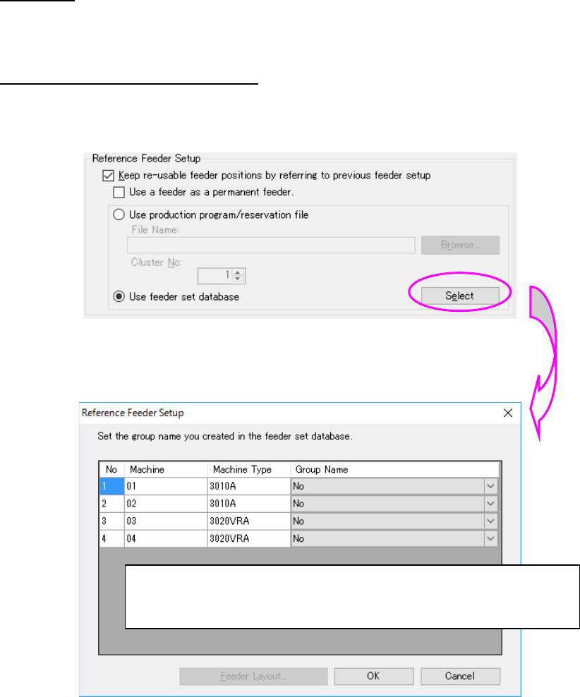
Reference to the feeder set database
When “Use of feeder set database” is selected, the feeder set of the feeder set database can be
referred as the reference feeder setup.
Figure 7.7-23 Use of feeder set database
The Reference feeder setup setting” dialog is displayed by “Setting.”
Figure 7.7-24 Reference feeder setup setting screen
“None” and the group name of a common bank type are displayed for the group.
A feeder set group name to be referred from can be selected from the combo box.
“OK”: The set contents are saves and completed.
“Cancel”: The set contents are aborted and completed.
“Feeder layout”: All the feeder layouts available for the line are displayed.
JaNets Instruction Manual 7. Program Editor
7-169
Others
The notes of the things that do not exist in an optimization option are described.
Notes on optimization of a production line including an RS-1 series machine
Manual nozzle attachment
You have to specify a nozzle that is to be attached in advance as a “Permanent Nozzle” when the
machine uses a manual nozzle attachment option.
The system handles such a machine so that “use setup nozzles” will be selected for the menu item
“Nozzle” regardless of the setting of the “Assignments” option tab to run a data consistency check
and perform optimization.
The setting of the menu item “Nozzle” is applied to the other machines assigned to the production
line.
Note on optimization to be performed for a production line including an
RS-1/JM-10 series
Permanent feeders
To prevent any head from interfering with a feeder or a component, set the “Head height at pro-
duction start” parameter of a production program for the machine main unit with the optimization
function. The “Feeder height,” which is one of the factors deciding this parameter, is calculated
based on the settings of the tray height and the tray depth both of which are saved in component
information of the Component Database. Therefore, if these settings are different from the actual
values, a head or a picked-up component may be in contact with a permanent feeder.
To use a permanent feeder of a tray holder, be sure to confirm that the settings of the Component
Database are consistent with the actual values. This also applies to the case in which you use the
“Used as a permanent feeder” option of the Reference Feeder Setup function.
Note of optimization to be performed for a production line including an
RS-1/RX-7 series
Restriction on height
In order to avoid a collision between the head and a placed component, the assignable compo-
nents on the upper stream side are limited if the lower stream side is under strict restriction.
For example, when the P16 heads of RX-7 are mounted on 2 machines, the placement of com-
ponents exceeding 3 mm is restricted on the upper stream side. Accordingly, even if the P8 head
of RX-7 is mounted on the first machine, a component with a height of 4 mm cannot be assigned
to the first machine.
In case of the “Max Part Height Option,” when the component height is restricted strictly with the
downstream side, components that can be assigned to the upstream side are restricted as well.
Interference with the PWB transport rail
When there are a placement position within 3 mm in the Y direction from the end of PWB, inter-
ference is caused to the PWB transport rail. As a result, an error occurs.