CP40 service manual.pdf - 第111页
2. Conveyor (CP-40) 8)Flow PCB to Check Proper Operation of Each Sensor. 7)Extend Pneumatic Air Hose to Place Stopper(Replace Newly) -.Refer to Fig. 4. #The Second Hose form the Right Among Air Blocks is for Place Stoppe…
2. Conveyor
(CP-40)
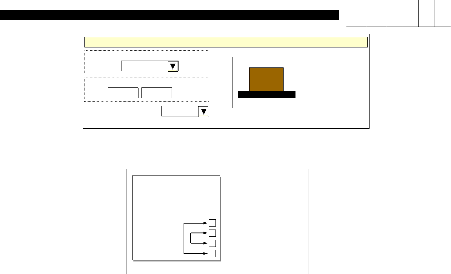
Origins
Coordinate System
Front Left
PCB Origin
603.375
Conveyor Direction
CCW
XY:
121.570
mm
X
Y
<Fig. 2> PCB Origin Setting
6)Exchange Locations of Sensors Connector on Conveyor I/F Board.
CN29(IN SENSOR)
CN30(WAIT SENSOR)
CN31(PLACE SENSOR)
CN32(OUT SENSOR)
Conveyor I/F Board
Version Date WA QA CA Note
00 Nov04 O O O
2. Conveyor
(CP-40)
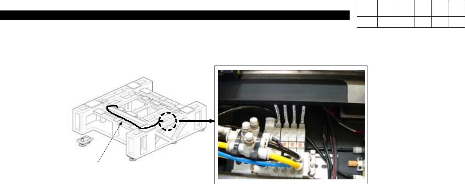
8)Flow PCB to Check Proper Operation of Each Sensor.
7)Extend Pneumatic Air Hose to Place Stopper(Replace Newly) -.Refer to Fig. 4.
#The Second Hose form the Right Among Air Blocks is for Place Stopper.
<Fig. 4> Place Stopper Pneumatic Line
AIR HOSE
AIR BLOCK
Version Date WA QA CA Note
00 Nov04 O O O
3. X-Y PART
(CP-40)
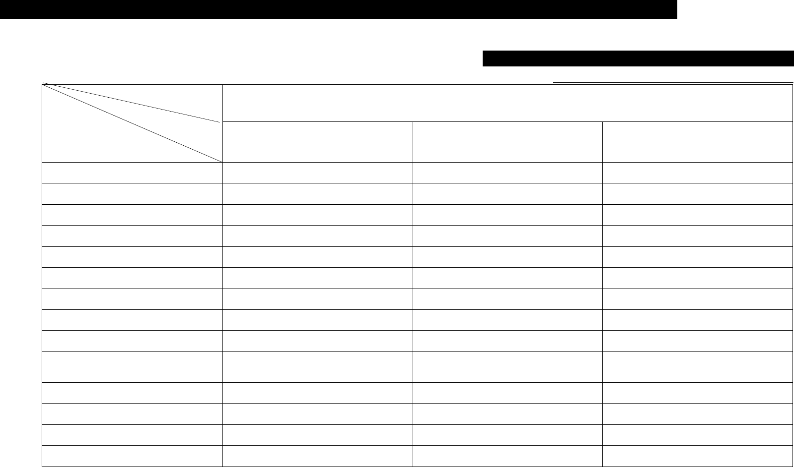
3-1. Trouble Diagnosis Guide Table
Malfunction
X-Y AXIS MOTOR SERVO DRIVER
Move Camera Offset 1
Ball Screw Replacement 8
X-Axis Motor Tension Setting 5
Linear Scale Cleaning 4
X-Axis S/W Limit Sensor Setting 6 1
Power Supply Check 7 2
Calibration 2
Connector Pin Check 3 1
Limit Sensor Check
Motor Driver Parameter Data
Modification
2
Servo Motor Drive Replacement 3
Motor Replacement 4
Home Sensor Replacement 3
Parts
Symptom
Check and Action
# Number Indicates Priority of Check Items.