CP40 service manual.pdf - 第118页
3. X-Y PART (CP-40) 4-5. Assemble [New Fiducial Outer LED Board Ass'y]. Note) -. Assemble it with the Bottom of Barrel Assy and LED Bo ttom of Outer LED Board Ass'y to be Horizontal(Refer to Below Picture). 4-6…
3. X-Y PART
(CP-40)
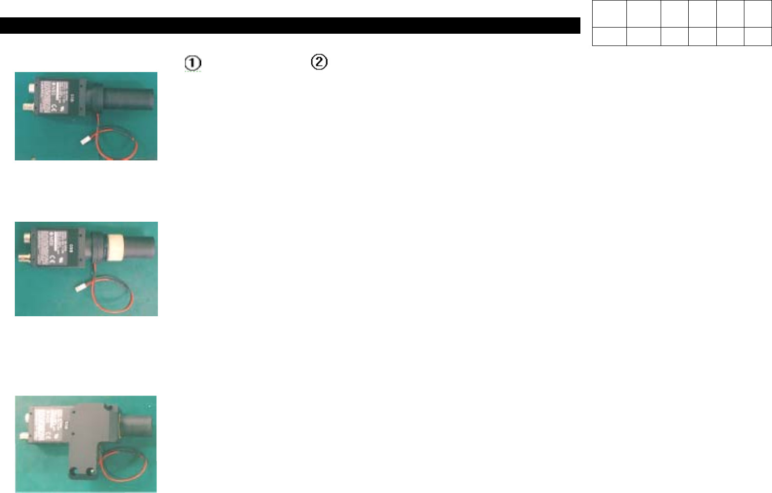
4-2. Assemble CCD Camera( ) and Barrel Ass'y( ).
4-3. Assemble [O-ring] and Camera Isolator.
Note) After Inserting Two O-rings into Barrel Ass'y, Insert Isolator to Stick to the End.
4-4. Assemble [Fiducial Camera Bracket].
Note) -.Insert O-ring Closely.
-.Assemble Camera Taking Care of the Direction of the Side with Label.
Version Date WA QA CA Note
00 Nov04 O O O
3. X-Y PART
(CP-40)
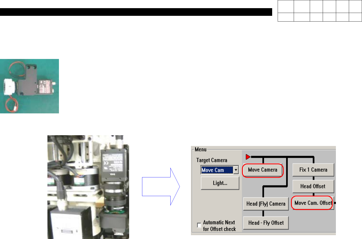
4-5. Assemble [New Fiducial Outer LED Board Ass'y].
Note) -. Assemble it with the Bottom of Barrel Assy and LED Bottom of Outer LED Board Ass'y to be Horizontal(Refer to
Below Picture).
4-6. After Attaching the Assembly, Calibrate Move Camera Again.
Note) Calibrate Move Camera & Move Cam. Offset Again.
Calibration
Version Date WA QA CA Note
00 Nov04 O O O

3. X-Y PART
(CP-40)
3-3-2. X-Axis Motor Replacement
1.Prior to Disconnecting Motor, Check Fixed State.
Especially Check Tension of Timing Belt Carefully and Remember Tension Value.
2.Disassemble Faulty Motor.
(Care should be Taken not to Miss Bolts.)
3.Install New Motor and Adjust Belt Tension.
(Adjust Tension to the Same Value with that of Faulty Motor.)
4.Perform Connection and Put On Power of Equipment.
5.Execute Home Action of Equipment.
6.The Origin of Motor may not be Proper.
(The Origin is Determined by Z Image of Motor.)
7.Now, Modify Limit Value, Feeder Origin and PCB Origin.
1.Limit Value Modification Method
a.In MMI Menu, Click Setup and then System Setup.
b.Input Password and Press OK.
c.Select the Seventh(Limit Position) from the Top and Click Edit.
d.When X, Y Limit Data is Shown, Input the Values of (X Left Value + (-20)) and (X Right Value + 20).
e.If Completing Input, Click OK and then Close.
Version Date WA QA CA Note
00 Nov04 O O O