CP40 service manual.pdf - 第119页
3. X-Y PART (CP-40) 3-3-2. X-Axis Motor Replacement 1.Prior to Disconnecting Motor, Check Fixed State. Especially Check Tension of Timing Belt Carefully and Remember Tension Value. 2.Disassemble F aulty Motor. (Care shou…
3. X-Y PART
(CP-40)
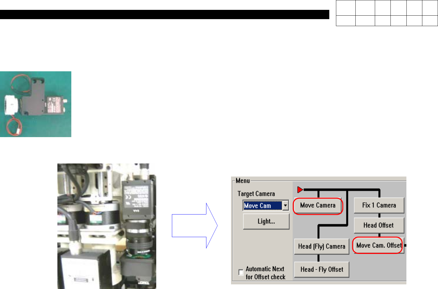
4-5. Assemble [New Fiducial Outer LED Board Ass'y].
Note) -. Assemble it with the Bottom of Barrel Assy and LED Bottom of Outer LED Board Ass'y to be Horizontal(Refer to
Below Picture).
4-6. After Attaching the Assembly, Calibrate Move Camera Again.
Note) Calibrate Move Camera & Move Cam. Offset Again.
Calibration
Version Date WA QA CA Note
00 Nov04 O O O

3. X-Y PART
(CP-40)
3-3-2. X-Axis Motor Replacement
1.Prior to Disconnecting Motor, Check Fixed State.
Especially Check Tension of Timing Belt Carefully and Remember Tension Value.
2.Disassemble Faulty Motor.
(Care should be Taken not to Miss Bolts.)
3.Install New Motor and Adjust Belt Tension.
(Adjust Tension to the Same Value with that of Faulty Motor.)
4.Perform Connection and Put On Power of Equipment.
5.Execute Home Action of Equipment.
6.The Origin of Motor may not be Proper.
(The Origin is Determined by Z Image of Motor.)
7.Now, Modify Limit Value, Feeder Origin and PCB Origin.
1.Limit Value Modification Method
a.In MMI Menu, Click Setup and then System Setup.
b.Input Password and Press OK.
c.Select the Seventh(Limit Position) from the Top and Click Edit.
d.When X, Y Limit Data is Shown, Input the Values of (X Left Value + (-20)) and (X Right Value + 20).
e.If Completing Input, Click OK and then Close.
Version Date WA QA CA Note
00 Nov04 O O O

3. X-Y PART
(CP-40)
f.In MMI Menu, Select View and Click Position Display.
(Position Window is Displayed on Screen.)
g.Using Jog Box, Move Slowly to X-Direction.
On Screen, Read Value in X-Axis Immediately before Error(Limit Error).
h.Press Ready Switch and Execute Homing.
i.Using Jog Box, Move Slowly to X+ Direction.
On Screen, Read Value in X-Axis Immediately before Error(Limit Error).
Value of G will be (-) Value and that of J will be (+) Value.
j.Input Values of (G+2) and (I-2) into D.
k.Click OK and Close to Finish.
2.Feeder Origin Setting
(After Recording the Existing Data)
a.In MMI Menu, Click Setup and then System Setup.
b.Input Password and Press OK.
c.Select the Second(Origins) from the Top and Click Edit.
d.Install Feeder with Parts on No.11 Feeder.
e.Using Jox Box, Align Camera with No.11 Feeder Pick Up Point.
f.Specify Teaching Device on Right-hand Center as Camera and Click Data in Front First Item of Feeder.
g.Press Get Pos on the Right.
h.Input Values of (Existing Value - 150) into X Value of Front First Data and the Existing Value into Y Value(X Value will be (-)
Value(Normal)).
i.Perform Identical Procedures For Rear.
j.Remember Difference of Data.
Version Date WA QA CA Note
00 Nov04 O O O