CP40 service manual.pdf - 第133页
4. Feeder Base & ANC (CP-40) 1. Faulty Feeder Unlock Sensor Replac ement (Replace Light-Emitting/Receiving Parts in Pairs.) 1) Replace Faulty Feeder Lock Sensor. Replace Light-Emitting/Receiving Parts in Pairs. 2) Se…
4. Feeder Base & ANC
(CP-40)
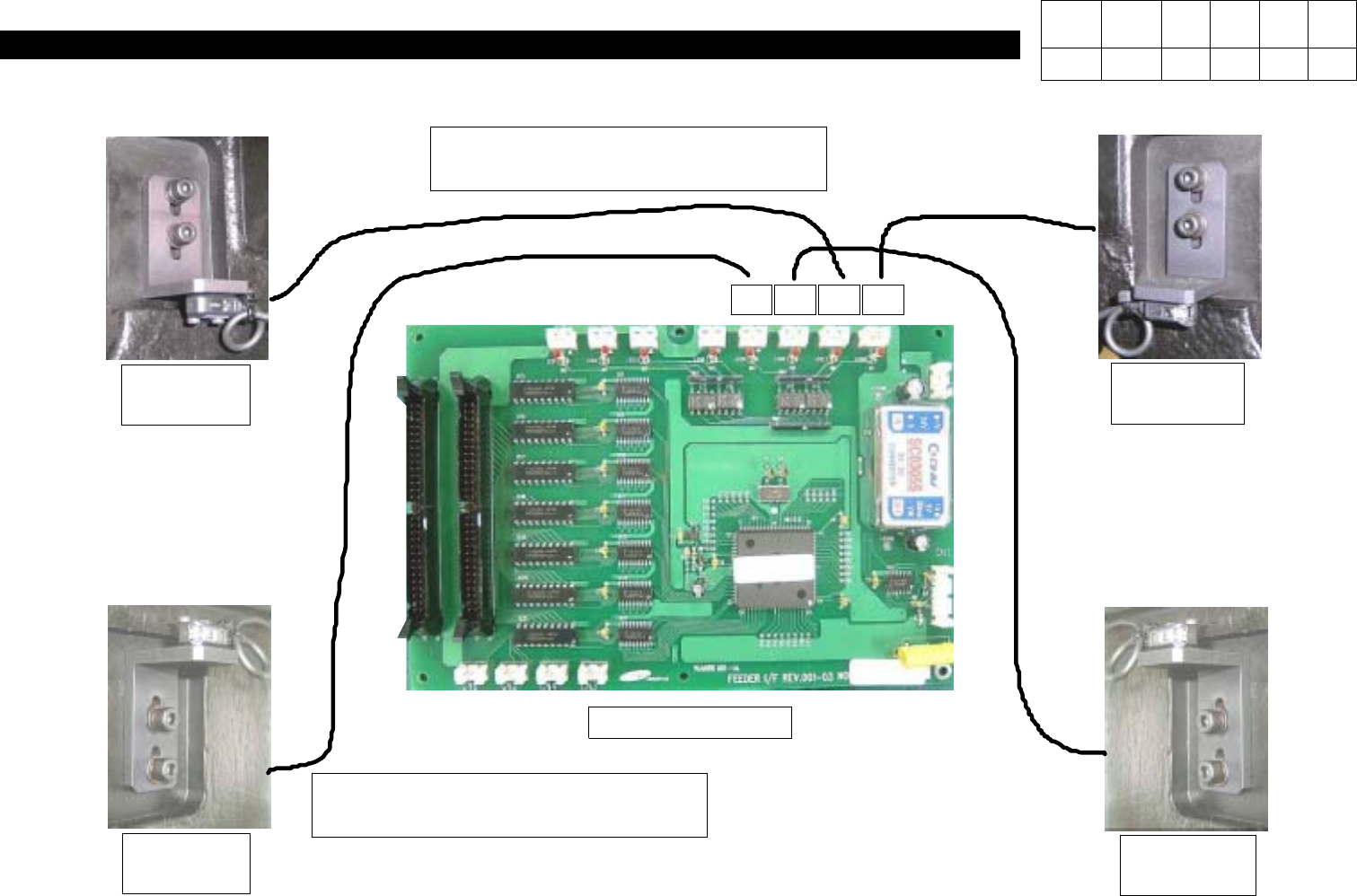
4-3-3. Feeder Unlock Sensor Replacement and Setting
11 12 13 14
Feeder I/F Board
Emitting
Light(Front)
Receiving
Light(Front)
Emitting
Light(Rear)
Receiving
Light(Rear)
Feeder Unlock Sensor Cable Ass'y
J2102111
Feeder Unlock Sensor Cable Ass'y
J2102109
Version Date WA QA CA Note
00 Nov04 O O O
4. Feeder Base & ANC
(CP-40)
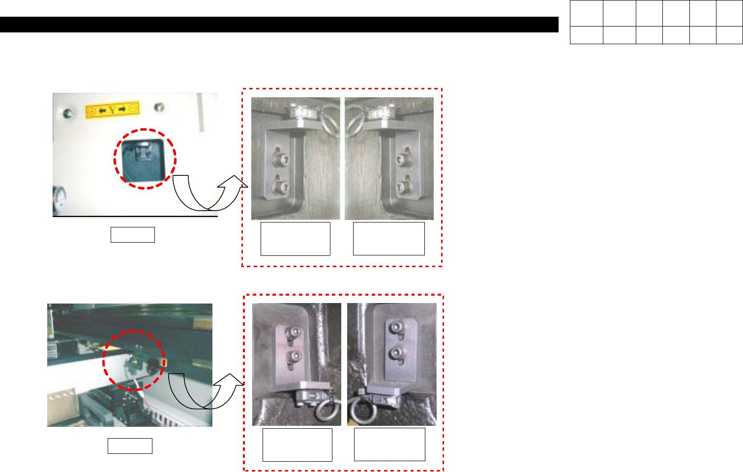
1. Faulty Feeder Unlock Sensor Replacement
(Replace Light-Emitting/Receiving Parts in
Pairs.)
1) Replace Faulty Feeder Lock Sensor.
Replace Light-Emitting/Receiving Parts in
Pairs.
2)
Set the Height with the Sensor Assembled
Temporarily.
3) Centering Feeder Base, Light-Receiving Part
is on the Right-hand and Light-Emitting Part
is on the Left-hand(It is Applied to Both the
Front and the Rear Identically).
Fig. 1
Fig. 2
Receiving
Light(Rear)
Emitting
Light(Rear)
Receiving
Light(Front)
Emitting
Light(Front)
Version Date WA QA CA Note
00 Nov04 O O O
4. Feeder Base & ANC
(CP-40)
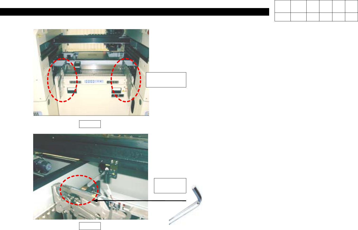
2. Feeder Unlock Sensor Height Setting
1) Install Two 8 mm Tape Feeders on Both Ends of
Feeder Base.
2) Adjust the Height of Light-Emitting/Receiving Parts
until Yellow LED of Light-Receiving Part is ON
(Refer to Fig. 3).
3) Install 2.5 mm L-Wrench on Feeder Guide of
Light-Receiving Part Front Feeder(refer to Fig. 4)
and Verify Yellow LED is OFF.
4) Adjust the Height until with L-Wrench Removed, LED
is ON and with L-Wrench Removed, LED is OFF.
Fig. 3
Fig. 4
2.5mm
L-Wrench
8mm
Tape Feeder
Version Date WA QA CA Note
00 Nov04 O O O