CP40 service manual.pdf - 第150页
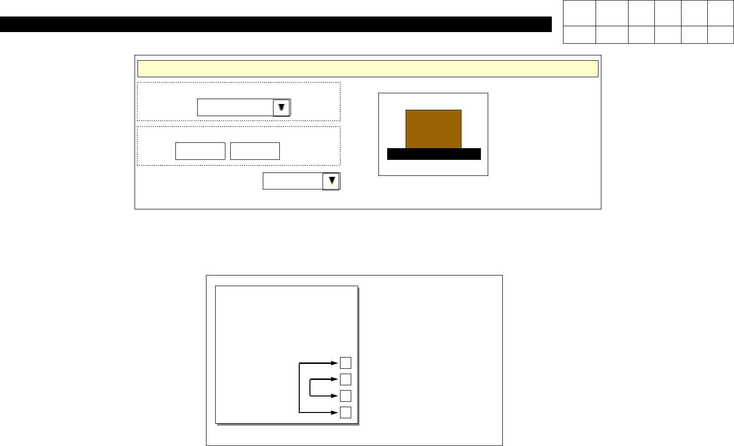
4. Feeder Base & ANC (CP-40) Origins Coordi nate Syste m Front Le ft PCB Origin 603.375 Conveyor Direction CCW XY: 121.570 mm X Y <Fig. 2> P CB Origin Setting 6)Exchange Locations of Sensor Connectors on Convey…
4. Feeder Base & ANC
(CP-40)
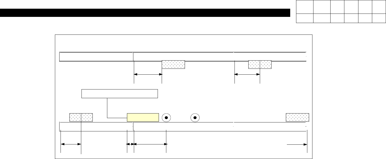
<Single-stage Conveyor> <2-stage Conveyor> <3-stage Conveyor>
OUT SENSOR PLACE STOPPER
HOLE
FIXER
INPUT SENSOR
#Based on White Block
PLACE SENSOR WAIT SENSOR
100mm 45mm
45mm 15mm 950mm 0mm
<Fig. 1> CP-40L(V) Conveyor Right => Left Assembly View
<Working Procedures>
1)As Shown in Above Figure, Secure Sensors on Each Position Properly.
2)Secure White Block(for Securing Place Stopper) Between Single-stage and 2-stage Conveyors according
to Each Dimension.
3)Secure Place Stopper on Left Block.
4)Exchange the Left and the Right of AC Motor.
5)Set PCB Origin to Front Left and the Direction of 2-stage Conveyor to CCW.
-.Refer to Fig. 2.
Version Date WA QA CA Note
00 Nov04 O O O
4-3-9. Conveyor Right => Left Change
4. Feeder Base & ANC
(CP-40)
Origins
Coordinate System
Front Left
PCB Origin
603.375
Conveyor Direction
CCW
XY:
121.570
mm
X
Y
<Fig. 2> PCB Origin Setting
6)Exchange Locations of Sensor Connectors on Conveyor I/F Board.
CN29(IN SENSOR)
CN30(WAIT SENSOR)
CN31(PLACE SENSOR)
CN32(OUT SENSOR)
Conveyor I/F Board
Version Date WA QA CA Note
00 Nov04 O O O
4. Feeder Base & ANC
(CP-40)
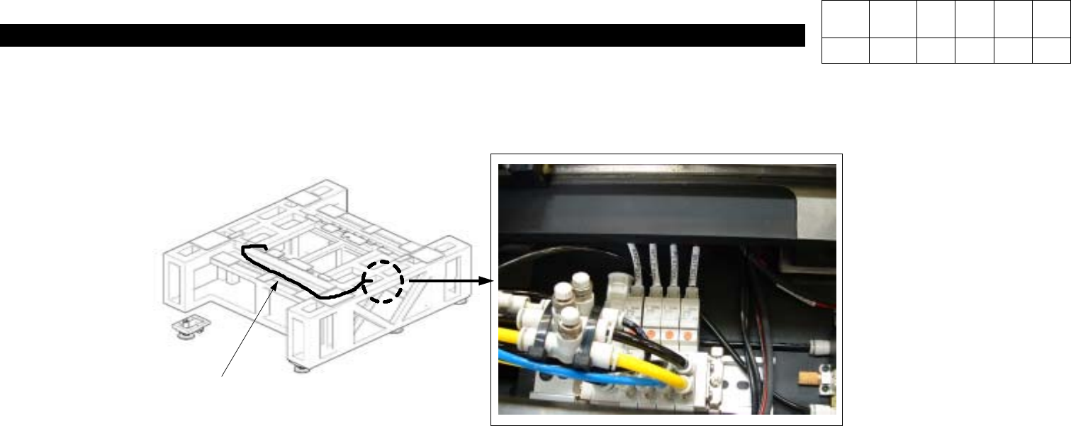
8)Flow PCB to Check Proper Operation of Each Sensor.
7)Extend Pneumatic Air Hose to Place Stopper(Replace Newly) -.Refer to Fig. 4.
#The Second Hose form the Right Among Air Blocks is for Place Stopper.
<Fig. 4> Place Stopper Pneumatic Line
AIR HOSE
AIR BLOCK
Version Date WA QA CA Note
00 Nov04 O O O