CP40 service manual.pdf - 第153页
5. Electric Device (CP-40) NO Symptom Possible Cause Error Co de Action Instr uctio n 1 Transforme r Malfunction Input Voltage is Low. Connect Disconnecte d Cable. 5-3-1 2 Noise Tighten Main Power Connec tor Bolts. 5-3-1…
5. Electric Device
(CP-40)
5-1. Trouble Diagnosis Guide Table
Malfunction
Trans Former Power Supply Op Panel Circuit Protect
CP Replacement 4
Power Supply Replacement 5
OP Panel SW Replacement 4
OP Panel SW Soldering Check 3
Lamp Replacement 3 5
Power Supply Cable Check
2
\
5
AC/DC Line Check 3 2 2 4
Cable Disconnection Check 4 1 3
Power Supply 24V Output Check 1
Main Power Input/output Check 1 1
Circuit Break Check 2
Parts
Symptom
Check and Action
# Number Indicates Priority of Check Items.
5. Electric Device
(CP-40)
NO Symptom Possible Cause Error Code Action
Instructio
n
1
Transformer Malfunction
Input Voltage is Low. Connect Disconnected Cable. 5-3-1
2 Noise Tighten Main Power Connector Bolts. 5-3-1
3
Power Supply
24V is not Output. Connect Disconnected 24VG and 24VP. 5-3-2
4 Bad Stick Feeder 24V AC/DC Lining 5-3-2
5 Front AC Power Malfunction Disconnect Cable. 5-3-2
6 When Checking I/O, 24V is Down. Modify CV CN 37 Pin. 2-3-2
7
OP Panel
Reset SW Always Remains ON. Replace Reset SW. 5-3-3
8
Functions of OP Panel SWs are
Exchanged.
Modify Soldering. 5-3-3
9 Ready SW Color is not Correct. Replace Lamp.
10 Main Panel SW Malfunction Modify Wiring.
11
Circuit Protect
Stick Feeder Malfunction Check and Replace CR9. 5-3-2
12 Servo Driver Malfunction Check and Replace Circuit Protect. 5-3-2
13 PC Malfunction Check and Replace CP1. 5-3-2
14 Step Driver Malfunction Check and Replace CR2-1. 5-3-2
15
16
17
5-2. Trouble Diagnosis
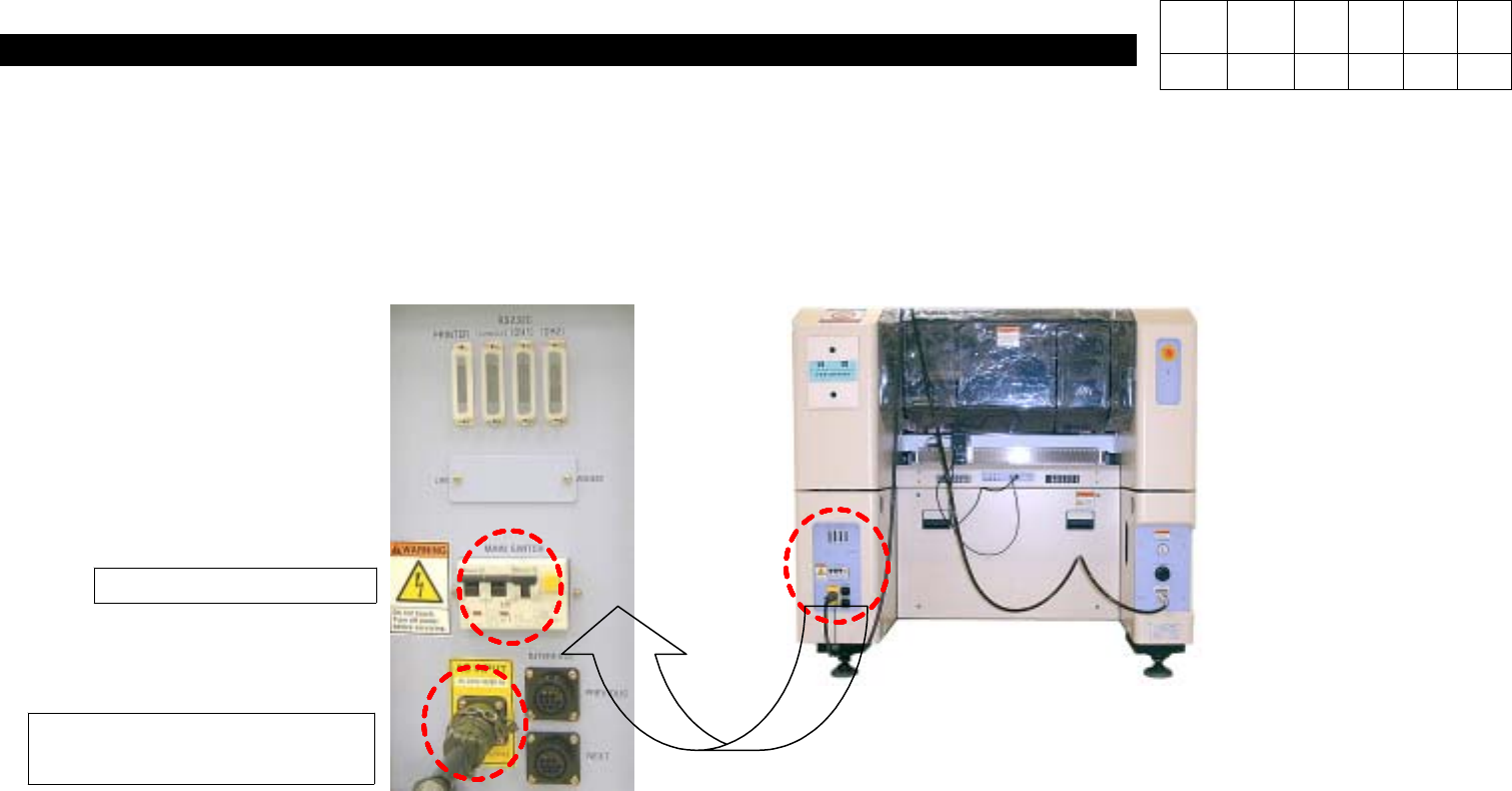
5. Electric Device
(CP-40)
5-3-1. Trans Former Replacement and Input Voltage Check
1. Close Program and Shut Circuit Break Off.
2. Disconnect Main Power Cable from Equipment.
2. Main Power Cable
Disconnection
Version Date WA QA CA Note
00 Nov04 O O O
1. Circuit Break Off