CP40 service manual.pdf - 第161页
5. Electric Device (CP-40) . SCM Bo ard Input Power (DC 5V +- 0.1V) Action : Power Supply #5 Power Con trol(DC 5V +- 0.1V) : Set to 5V. After O pening the Lower Left-hand Cover of the Front of Equipment and Set 5V Power …
5. Electric Device
(CP-40)
Version Date WA QA CA Note
00 Nov04 O O O
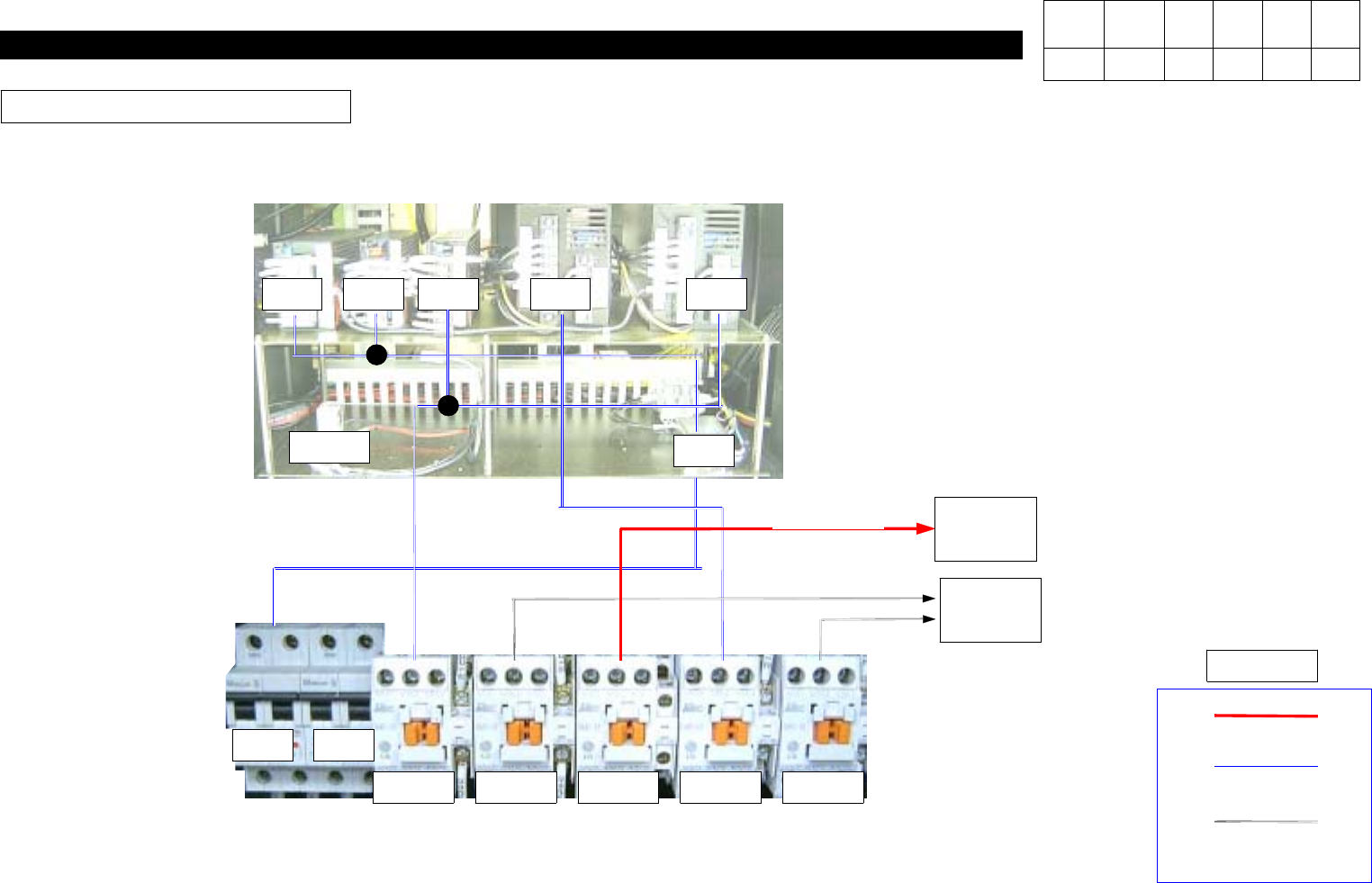
PS Input Power Block Diagram
PS1 PS2 PS5 PS4 PS3
CR-3
NF2
CP1 CP2
CR1-1 CR1-2 CR9 CR2-1 CR2-2
AC220V
AC100V
24V
Legend
SERVO
DRIVER
STICK
FEEDER
AC24V
AC100V
AC220V
5. Electric Device
(CP-40)
. SCM Board Input Power (DC 5V +- 0.1V)
Action :
Power Supply #5 Power Control(DC 5V +- 0.1V) : Set to 5V.
After Opening the Lower Left-hand Cover of the Front of Equipment and Set 5V Power Terminal of the Third Power
Supply(SA100-BDB) among Five Power Supplies to be within
DC 5V +- 0.1 V
Using Digital Tester.
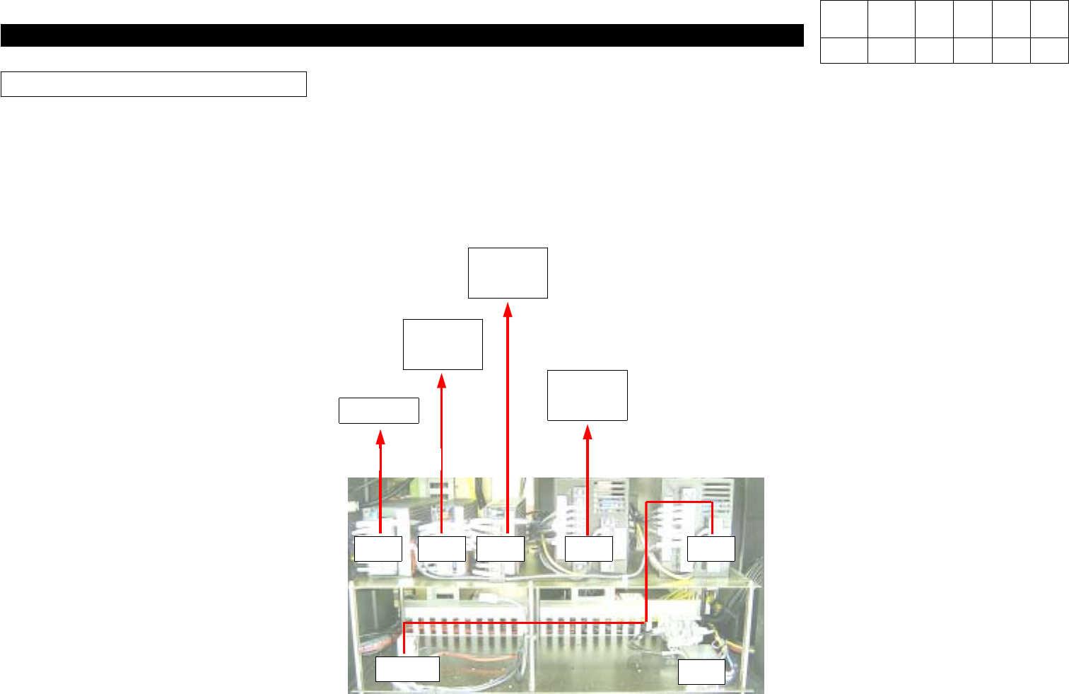
PS Output Power Block Diagram
PS1 PS2 PS5 PS4 PS3
CR-3
NF2
RACK
+5V
RACK
SUB I/F
+-12V
+24V
QA DSP
B/D
+- 5V
+12V
STEP
DRIVER
+24V
Version Date WA QA CA Note
00 Nov04 O O O
5. Electric Device
(CP-40)
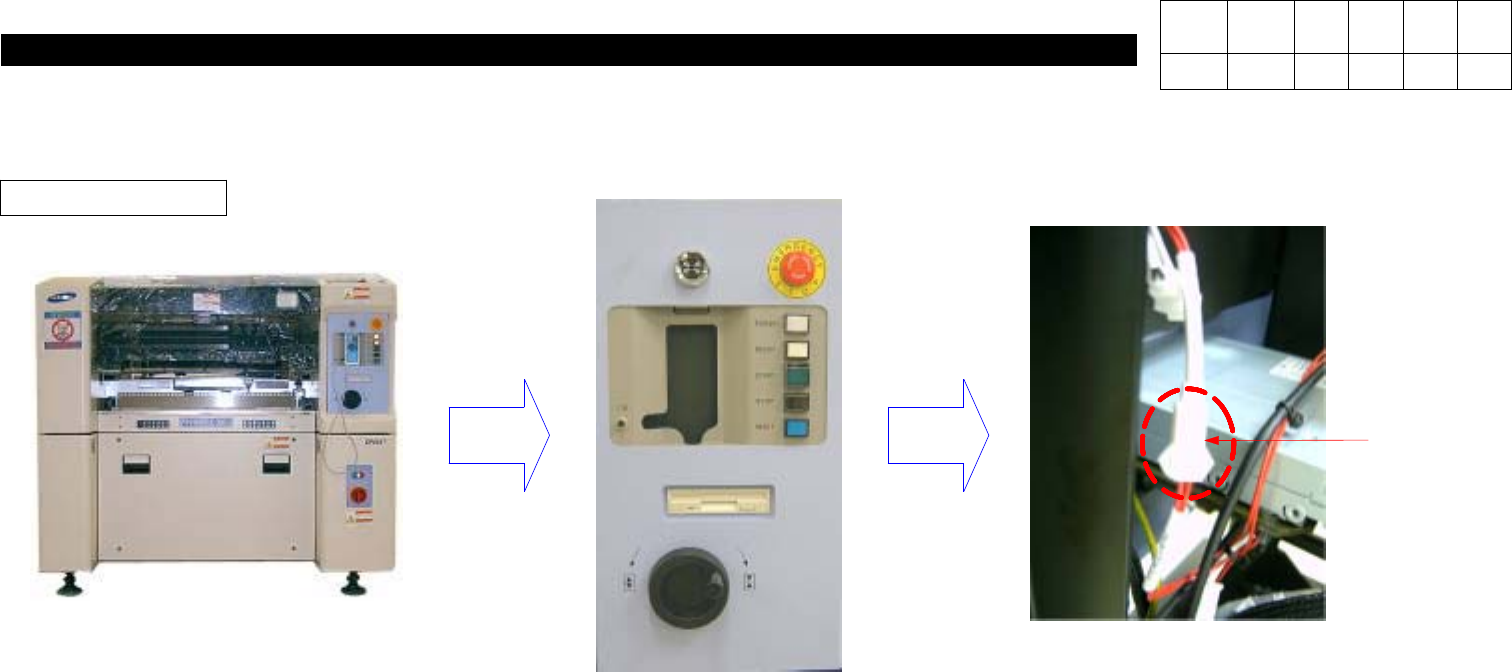
5-3-3. Op Panel Check
Front EMG Check
1. If Ready Lamp does not still Light On even with Power Supplied, Check EMG for Contact Status.
2. As Shown in the above Figure, Open Front Cover.
3. Check EMG Connector(Red Wire) in Back of Front OP Panel for Connection.
Front EMG
Connector
Version Date WA QA CA Note
00 Nov04 O O O