CP40 service manual.pdf - 第88页
1. Head Part (CP-40) 1. Click "Setup"=> "Diagnostics" => "Vacuum Pressure Level" in MMI. 2. Set Head 1~3 to ON. 3. Block Bottom of Comp Ass'y of Head with Finger and Verify Level …
1. Head Part
(CP-40)
(Fig. 3)
(Adjustment Procedures)
9)
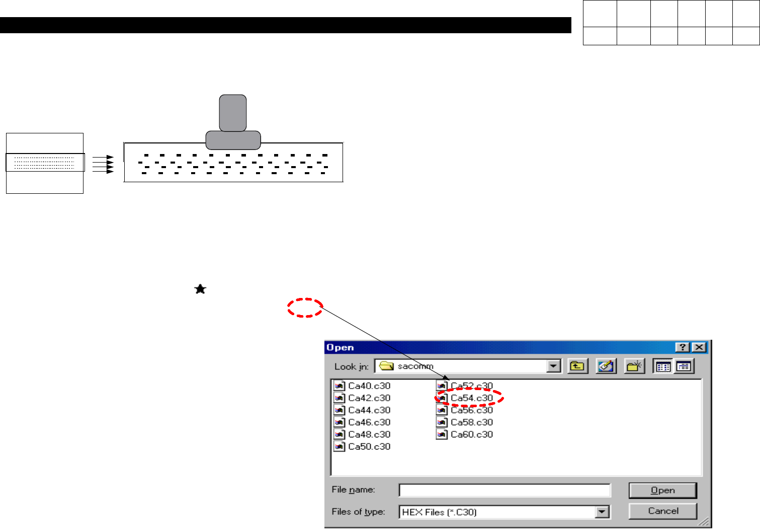
Using a Fixture(with Bolt Mark Inside), Align Aligner with WA Light.
10) At IMAGE => EDGE, Raise the Fixture Up to Indicate Figures on Both Sides(Refer
to Fig. 2).
11) While Rotating R-Axis, Make Five Digits on Both Sides Indicated Almost Similarly.
12) Download File to Save Average Distance(Rounding Off the Numbers to Three
Digits) as shown in Fig. 2 .
Example)
Average Distance = 115.31 => 5.3
13) Press SW2 Again and Set SW1 to Down.
ALIGNER
Version Date WA QA CA Note
00 Nov04 O O O
1. Head Part
(CP-40)
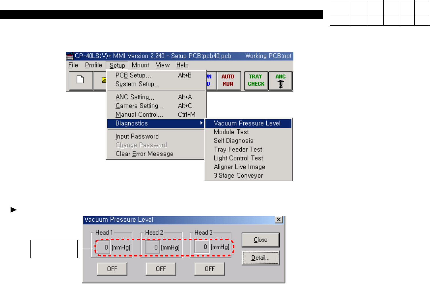
1. Click "Setup"=> "Diagnostics" => "Vacuum Pressure Level" in MMI.
2. Set Head 1~3 to ON.
3. Block Bottom of Comp Ass'y of Head with Finger and Verify Level Value.
When the Value is Under 560 [mmHg], Adjust it as follows.
560 [mmHg]
Version Date WA QA CA Note
00 Nov04 O O O
1-3-4. Vacuum Level Adjustment
1. Head Part
(CP-40)
Version Date WA QA CA Note
00 Nov04 O O O
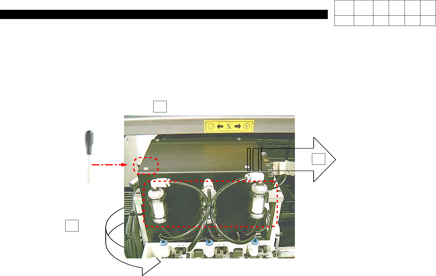
<Adjustment Method>
1. Using Teaching Box, Move Head to Rear Acrylic Cover.
2. Loosen Four M3*6 Toras Screws on the Top of Head.
3. Pull Three Filters on the Front.
4. Remove Head Cover.
2
3
Remove Four M3 * 6 4ea Toras.
Pull Three Vacuum Filter.
J6708006A
Remove Head Cover.
4